CONSTRUCTION PAUSED - I shifted work to the LX521 when it was announced.
The Orion loudspeaker is the brainchild of Siegfried Linkwitz. It is offered as a DIY project, and also as completed loudspeakers. Wood Artistry in the USA is the chief fabricator for premade Orion loudspeakers in North America, and they sell the Orion 4. I am building the Orion 3.4, which uses the same drivers, but has a slightly different outside shape, and the older but tried-and-true H-frame woofer baffle. Both versions should sound the same.
This loudspeaker is a dipole, which means that the sound coming from the back closely matches the sound from the front. At 90 degrees from the listening axis, the front and rear output combine phase to cancel each other. This means that much less sound energy is being radiated sideways, and that the reflections of sound from room walls will differ from familiar box-style loudspeakers.
Build Log
The following steps outline the fabrication, and assembly of this set of Orions. There are occasionally some small departures from the official published design, but the modifications were done with the philosophy of causing minimal impact to the sound.
Note that I will not disclose critical dimensions or other intellectual property concerning the Orions on this page.
Click any picture below to enlarge (some not functional yet)...
|
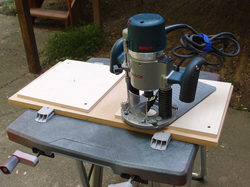
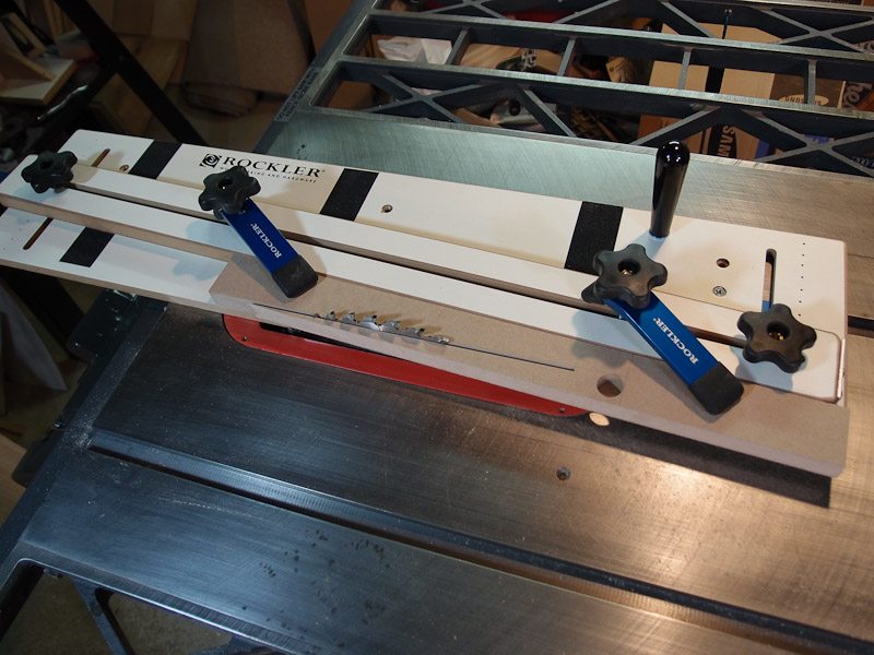
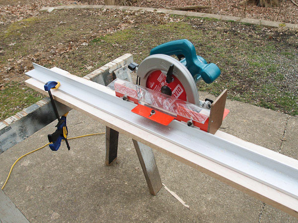
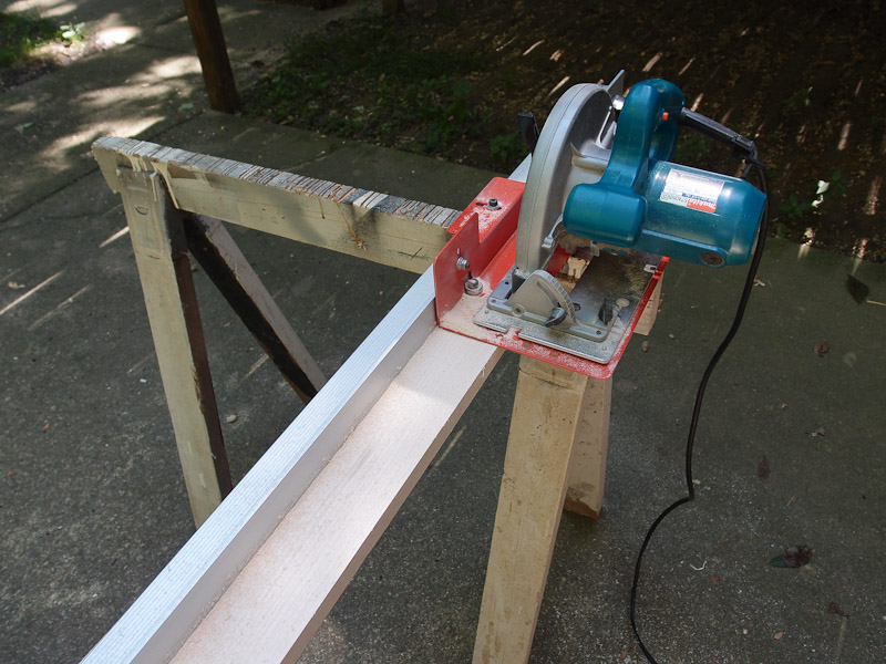
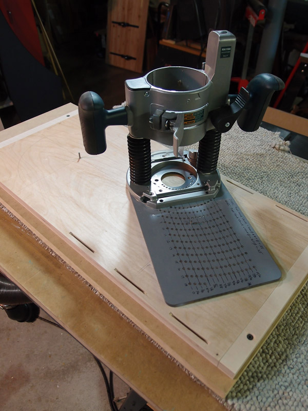
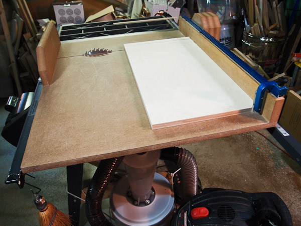
Toys, er... Tools What good is a project that doesn't include acquiring some new tools? This project was certainly rewarding in that regard. From top to bottom, a track saw, a crosscut sled, a router table, and an edge shooting board (complete with some rebuilt hand planes). I purchased the track saw system from Penn State Industries, but found that the ball bearing guides for it clogged very easily with sawdust. I fabricated a bent acrylic dust shield that did the trick, and I use it to square up one edge of rough lumber for use on the table saw. I wanted to build a large-ish crosscut sled for my table saw for precise cuts, and it's worth its weight in gold. (It IS heavy, so that would be a lot of gold!). It is large enough to hold a 2 foot piece of work from front to back, and I've even used it to rip some short boards because it is so stable. It was well worth the time and effort to make. Next, I purchased a Rockler router top and fence and needed a stand for it. I seized an opportunity when one of the woodworking magazines published plans for the router cabinet shown. It keeps dust and noise down and I can work indoors. It's made mostly of MDF and painted. I had planned to fabricate the side panels from wood instead of MDF, and needed a way to edge boards for a solid glue-up. As you will see, my baffle is hard maple boards glued up to the size needed, but I copped out and used MDF for the side panels - for now. I may rebuild these someday to use wood side panels. It's pretty bad when you plan a rebuild before even finishing! |
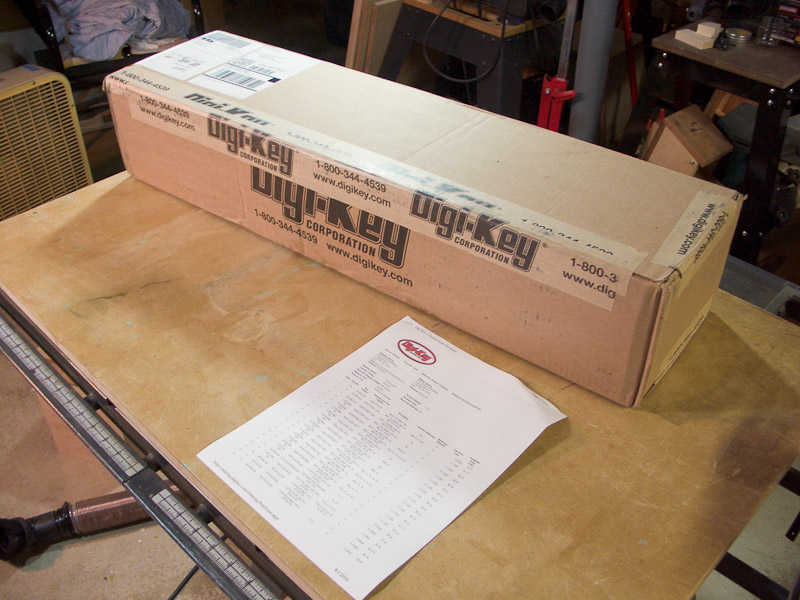 |
After ordering the plans
and circuit boards from Linkwitz Labs, I placed an order for the electronic
parts with Digikey. Shortly after I placed this order, some revisions to
the plans were made and new parts were ordered. More changes, more
parts.
I had picked a time when rapid changes were occurring. While change is good, my timing could have been a little better. Things have settled down as of this writing. |
-800px.jpg)
|
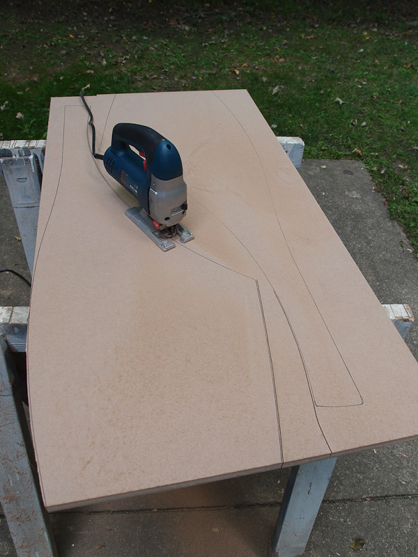
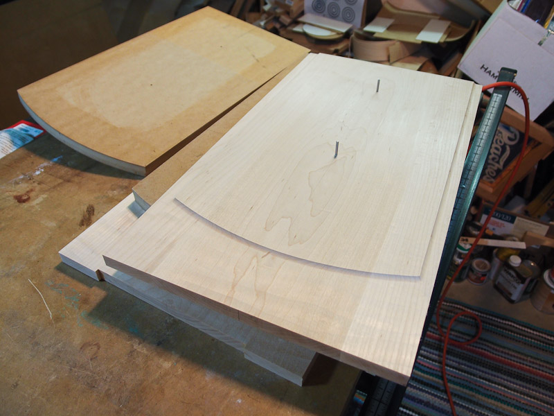
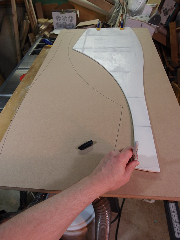
Laying Out Side Panel
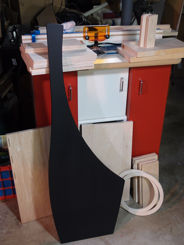
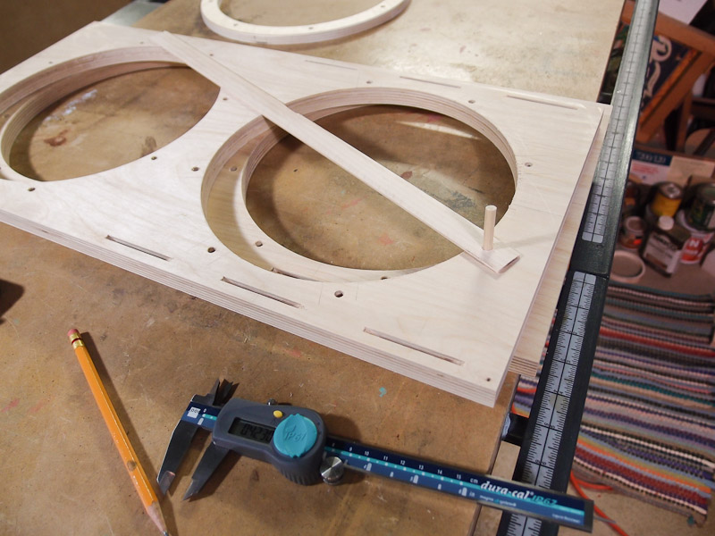
Shapes One of the distinctive features of the Orion is its shape. It is not a box speaker, and has a lot of curves in its shape. The side panels in particular are large and curvy. As you might imagine, it is smart to make a template first, then base the real panels on the template. I used some Masonite for the template material. In this photo, I've applied some white paint over the dark brown so I could see the pencil markings for cutting. I ran out of paint before I covered the whole panel, but it still helped. Some of the specified radii are large, so I bought a tape measure compass to help (more tools!). While cheaply made, it still got the job done. I suppose a piece of string with a pencil tied to one end would have worked too, but then there would be no tool to buy. This layout work required a large space as you can see by all the measuring devices being pressed into service. The shape is proprietary, so dimensions in the pictures may be obscured on purpose. |
-800px.jpg)
|
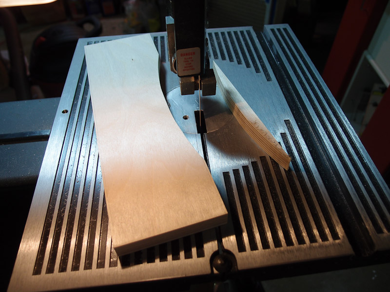
Side Panel Template
Fabrication I used my band saw to make the cuts as closely to the line as I could, but left a little to be sanded or cut away. I put a small block plane to use on the outside curves, and used a drum sander in my drill press to reach the inside curves. I finished up by hand-sanding the edges smooth. |
-800px.jpg)
|
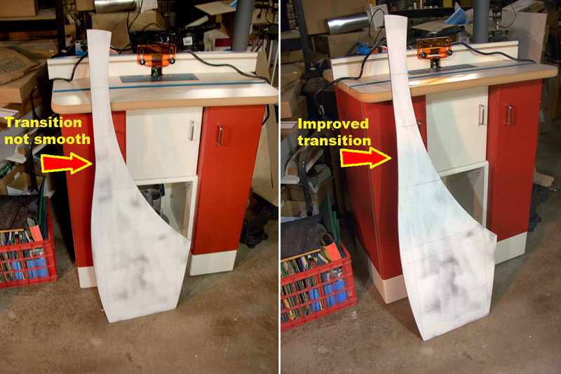
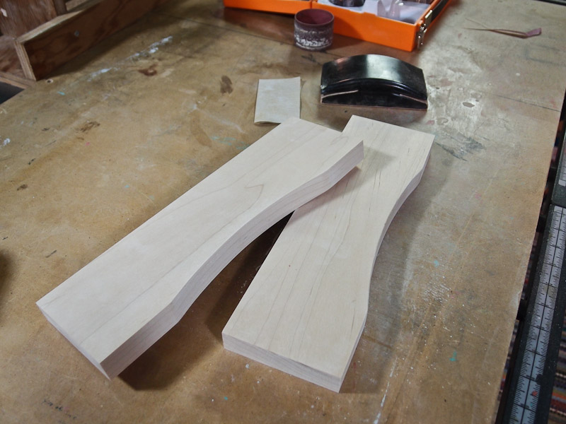
Minor Template Rework I thought that there was an odd transition on the front edge between the rounded bottom and the top half that looked odd. We can't have that, so I did surgery on the template to smooth the transition. First, I cut out the offending section away leaving a dovetail opening in which to fit the new material. I test fitted the new piece, then glued it into place. It was left very proud as you can see. Using French curves left over from my old drafting days, I formed a more gentle transition between the top and the bottom sections of the side panel. This was cut on the band saw and smoothed to the new pencil line. A new dab of white paint to hide the joint showed it to be perfect! The last photo in this group shows the before and after template shape. This template was used to form the four side panels for the speaker. Pictures and description will follow later. If I were doing this again, I'd make the first template out of 1/4" Masonite as I've shown, but I'd use this first template to make another from thicker MDF for actual use for cutting side panels. Tracking a thin template with the router was a bit nerve racking. |
|
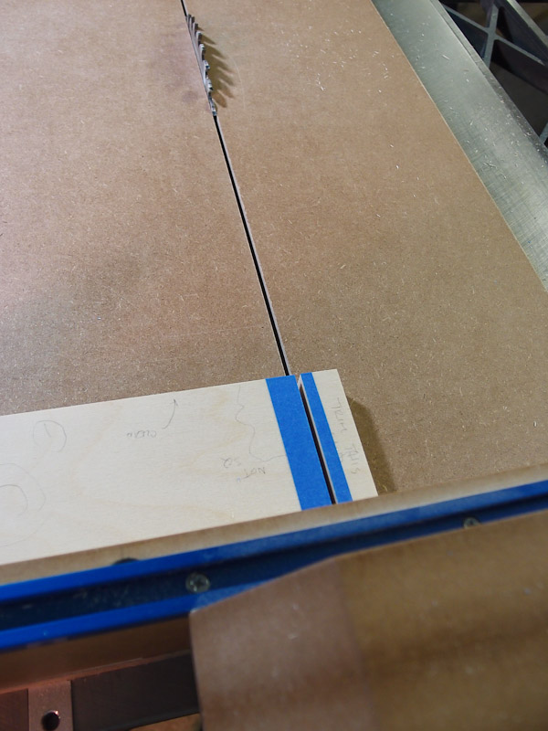
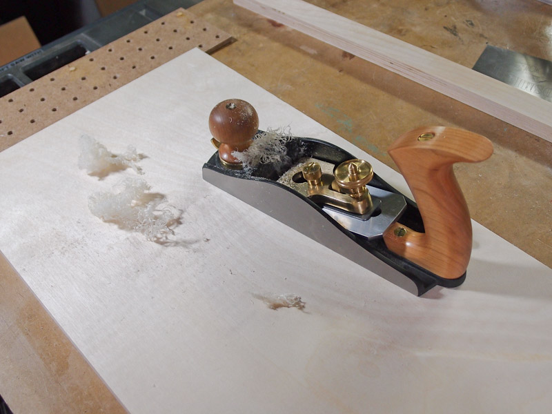
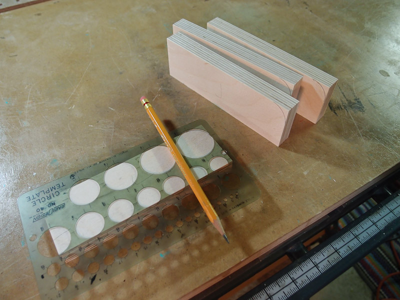
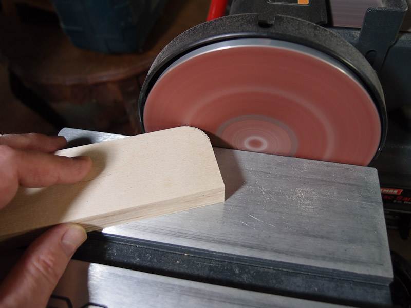
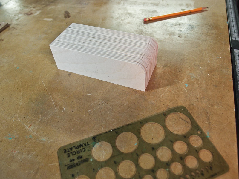
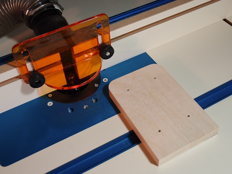
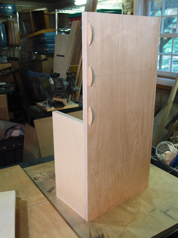
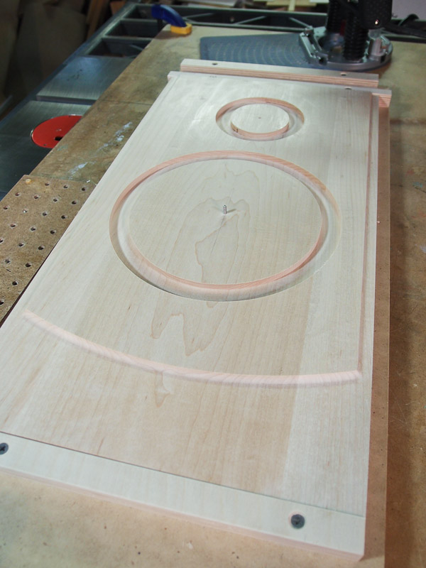
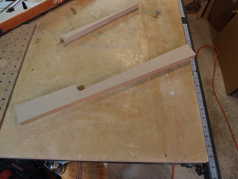
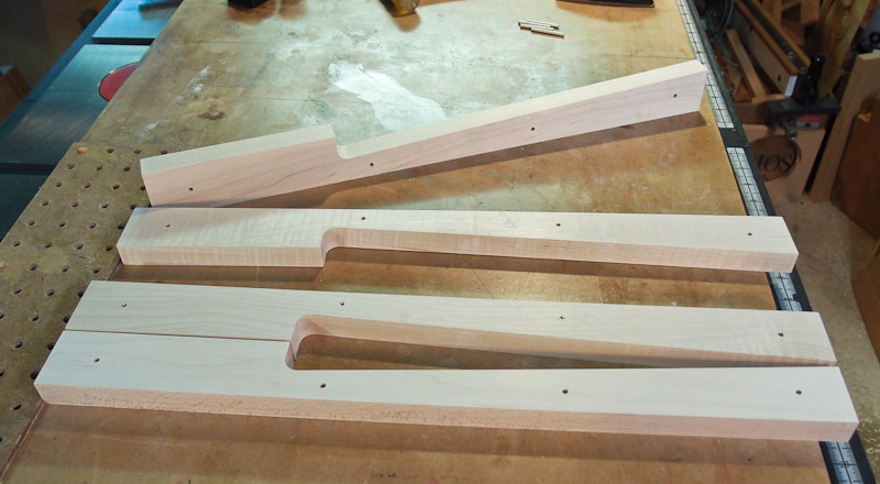
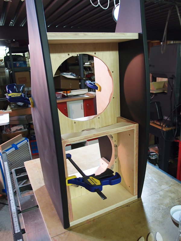
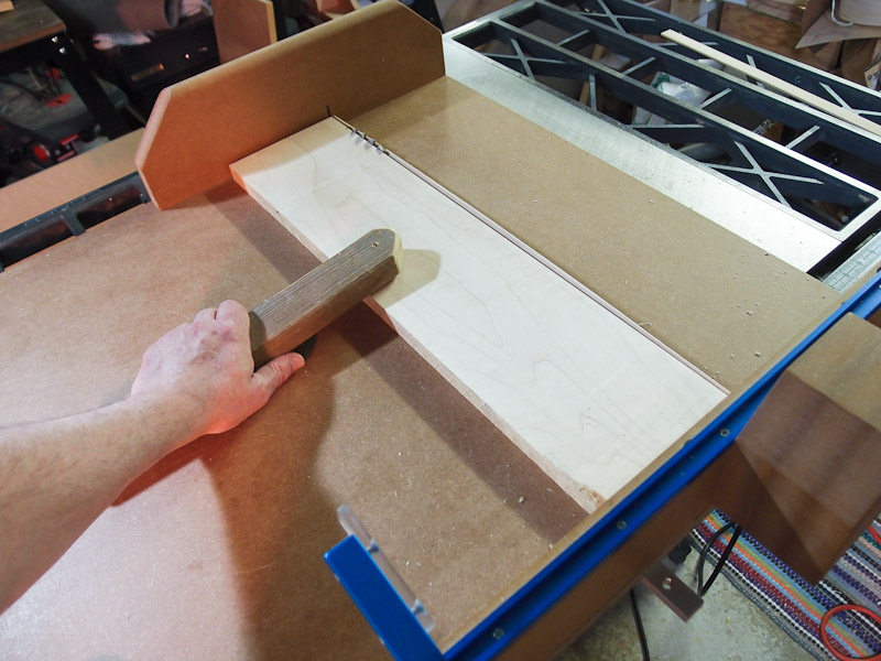
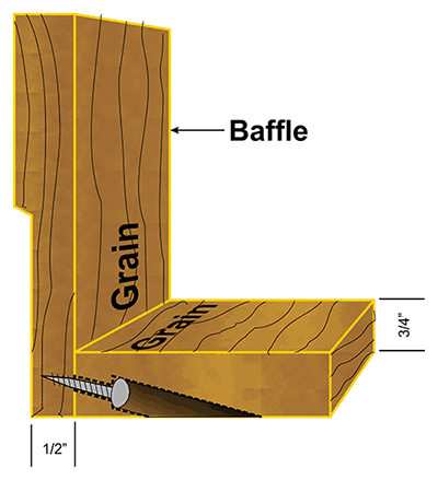
Woofer box fabrication While I could have attempted to make the newer W-frame woofer as sold by Wood Artistry, I preferred the appearance of the traditional H-frame Orion. Also, plans weren't available for the W-frame when I began, and I didn't want to bother reverse engineering the Orion 4. Now however, the plans are available to any Orion owner who wishes to retrofit. I drew my line in the sand at the older design. I began cutting 3/4-inch Baltic birch to the sizes given in the plans to assemble the woofer box. The crosscut sled helped keep things very square. Occasionally, I'd tape a cut line to prevent splintering of the plywood. One aspect of the Baltic birch could use some improvement - the surface smoothness. Mill marks from a planing operation were apparent, and I was concerned that they would detract from the finished product. I used a smoothing plane (another new toy!) to remove the mill marks. It's not foolproof, and I went through a considerable learning curve with this tool to prevent tearout of the surface. The optimal planing direction to reduce tearout is hard to predict with the thin plies. But it worked in the end. I deviated from the plans somewhat to dress up the rectangular slabs of wood. For example, one leg that supports the vertical woofer baffle got a dandy radius at the exposed end instead of just having square corners. Using an old drafting template from my earlier job, I drew the desired curve, then band sawed it close to the line. A light touch-up on a disk sander brought the curve to the pencil line very nicely. Using the router table, I also put a 1/8" chamfer on the exposed edge. I did two at once to prevent tearout at the exit end of the piece. The last photo shows how they were arranged on the router table for chamfering. |
|
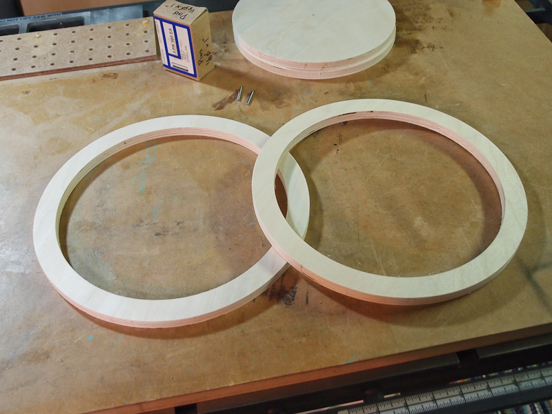
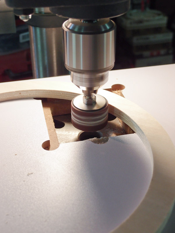
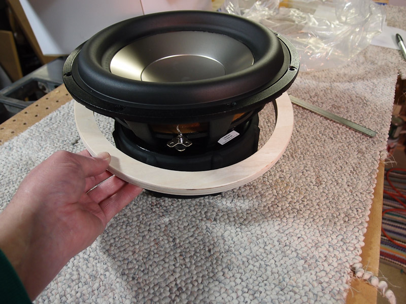
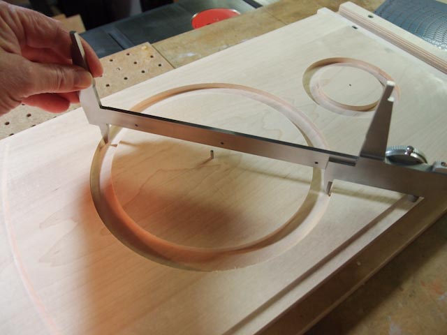
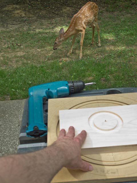
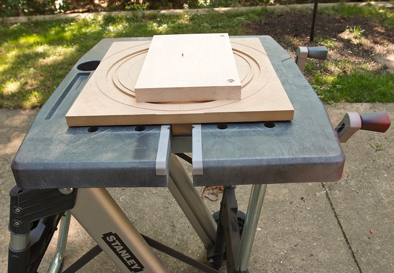
While I chose to build the
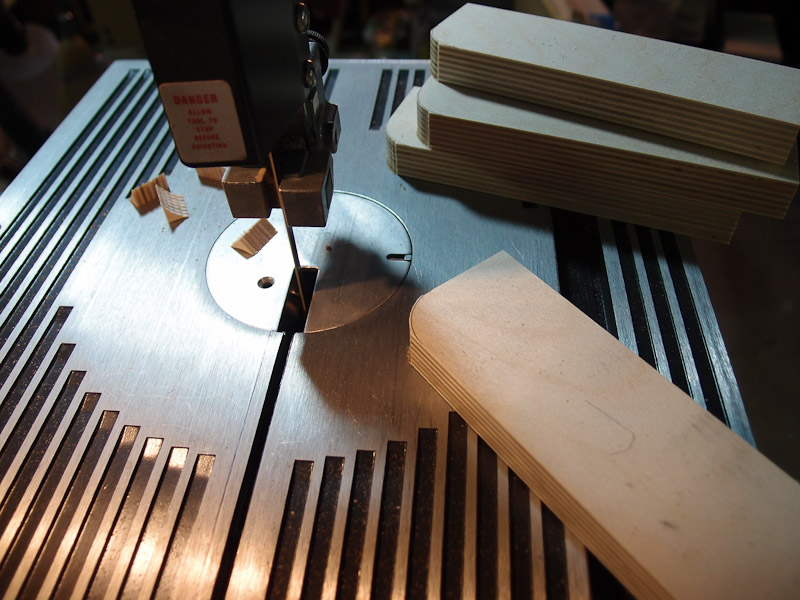
Experienced speaker builders will recognize the steps for making the spacer rings. A 1/8" hole for a pin is drilled in the center for the Jasper circle guide jig mounted to a plunge router. The work material is secured to a backer board (in my case cheap MDF) so it can't come loose as the last cutting pass is made. The backer board also provides clean cuts on the back side of the rings. Once they were cut, I mounted a drum sanding disk to my drill press to smooth the inside surface. These rings will be mounted (glued in my case) to the woofer H-frame baffle to space the bottom woofer back so that its magnet doesn't protrude past the plane of the grill cloth. |
|
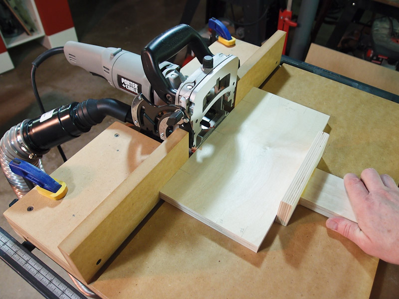
I began fabricating more
woofer box parts with the idea that I'd use biscuits and glue to join
the pieces of Baltic birch plywood together. I don't use the biscuits
for additional strength in the glue joint, but to help me align the
parts during glue-up. It also makes dry fitting a snap. You can see in the first photo how I use the crosscut sled to rip long boards to width. I found that this is convenient, but I will investigate a better method for holding the work piece securely in place. I occasionally used a plane to dimension and smooth the cut edges of mating pairs of braces so that they exactly match. I have a jig for my biscuit cutter that speeds work and improves accuracy. I marked and cut biscuit slots in the appropriate pieces using it. As I'd finish with a pair of mating parts, I'd dry fit right away to spot any mistakes. There were none, and this went smoothly. Note that the woofer holes had not been cut yet. I was still awaiting backordered drivers from Madisound before cutting openings. At this point, I set aside the woofer box for a while. |
|
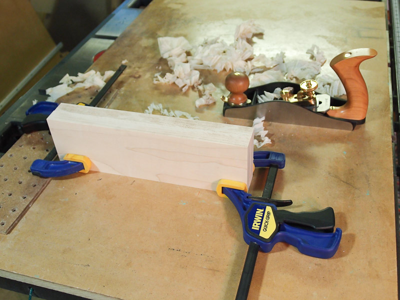
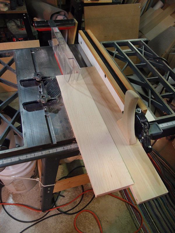
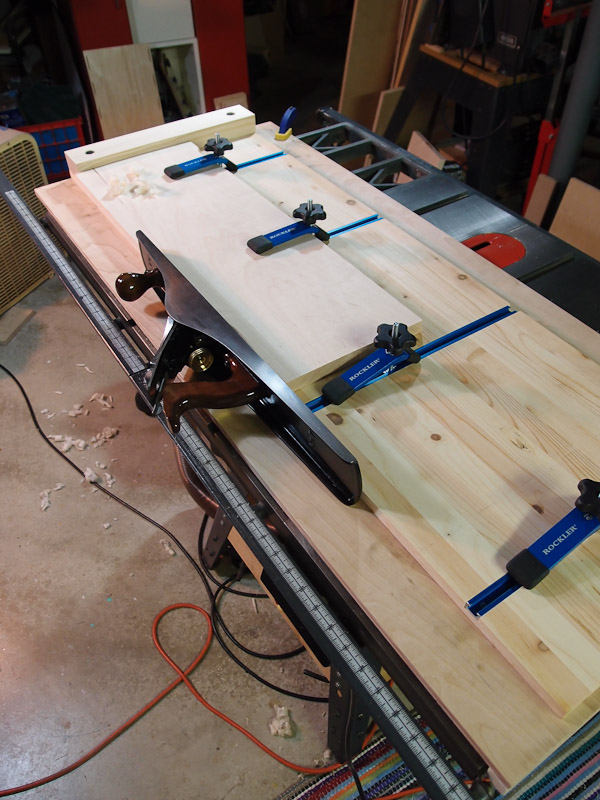
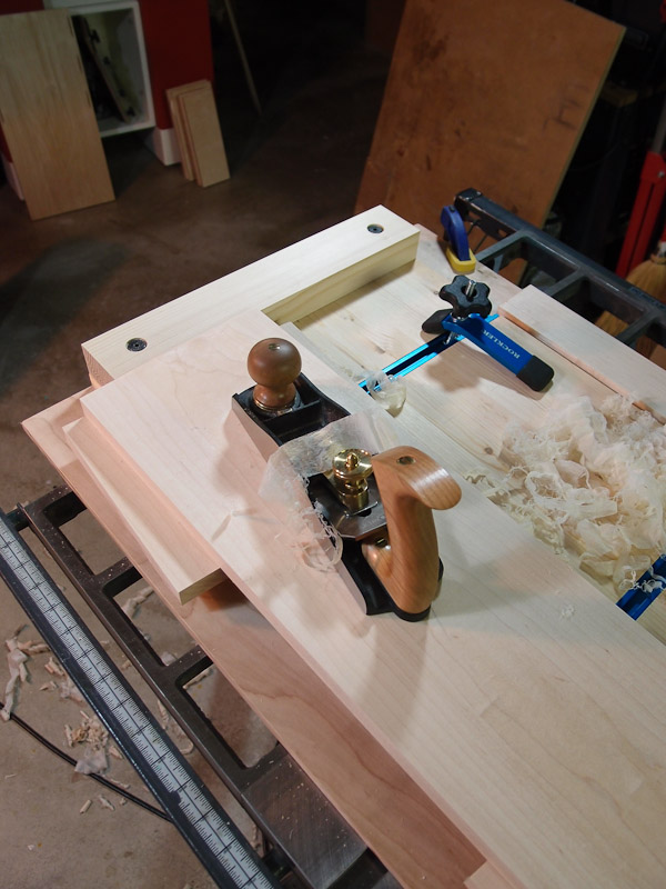
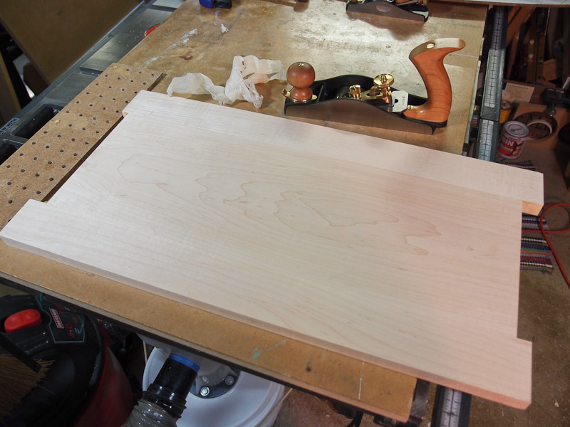
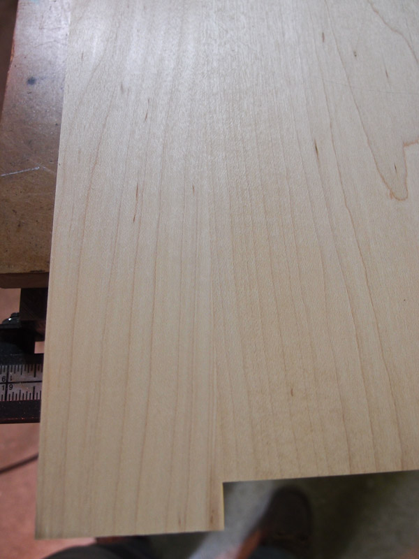
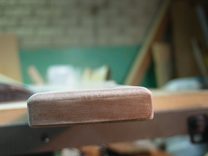
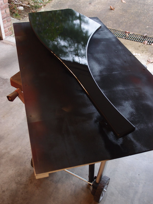
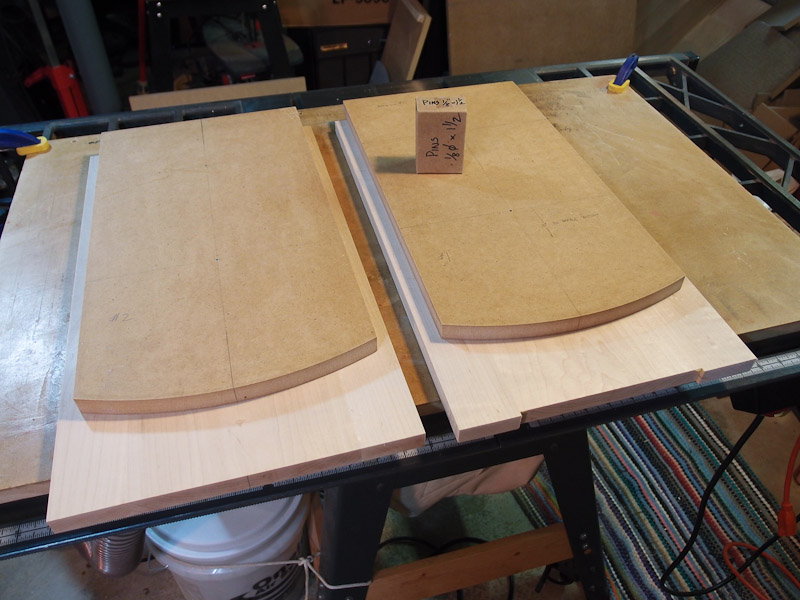
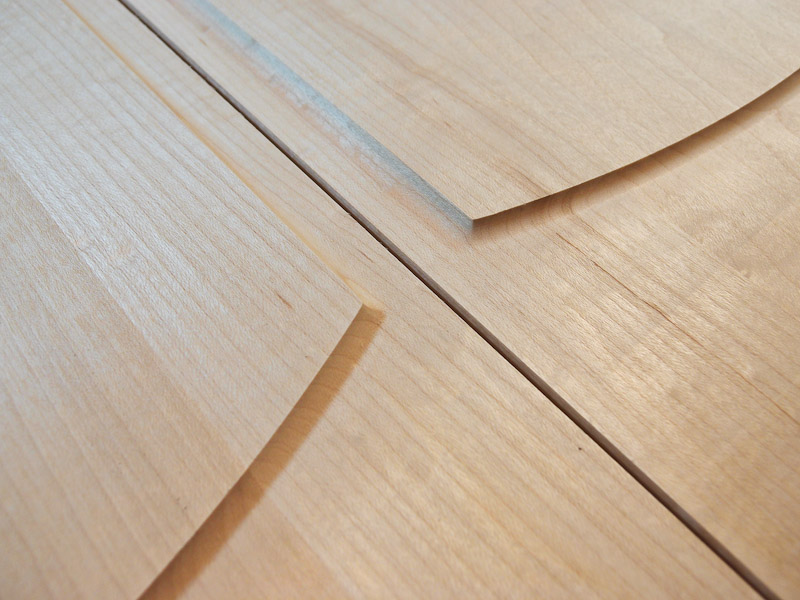
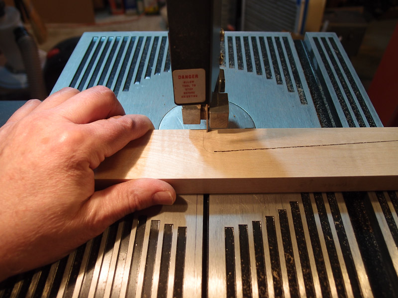
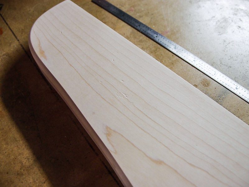
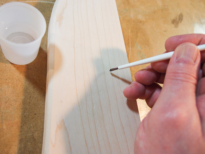
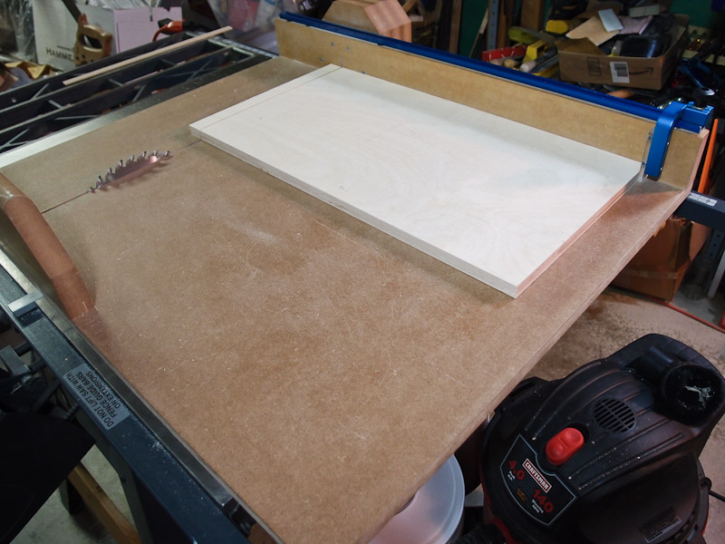
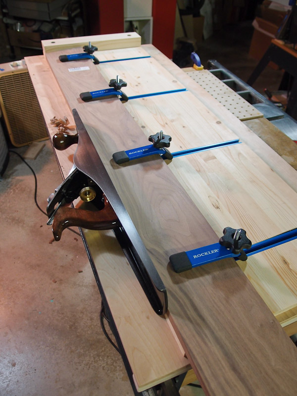
Baffle Glue-up I had purchased some 4/4 hard maple for the baffle, but the edges were roughly cut. I had to clean them up before I could rip them to width on the table saw. I used the track saw outdoors to do this (there's not enough room in my shop for this - it's really cramped indoors!) This is when I discovered that the bearings tended to jam with sawdust because of the way the blade dumped everything onto the track. I fixed this tool's deficiency later on with a plastic shield that kept sawdust away from the bearings and track. I did manage to get a fairly straight edge on the maple boards regardless. Next I brought the edged boards to the table saw for ripping to approximately the width I needed. The baffle will be comprised of a three boards glued together. The center board was wider than the two boards that flanked it. To get a very accurate edge for gluing, I built a large shooting board for my newly rebuilt Stanley #7 hand plane. The shooting board has clamps for securing the work in place, and gives me a very accurate 90-degree edge. I realize that serious woodworkers have a workbench on which to do this sort of work, but as you can see, my table saw top is my bench. I did use the smoothing plane to improve the surface of the boards before gluing. I'm not sure how smart this was because I had to plane them again after gluing to get a perfectly flat surface. I used biscuits on one of the boards, but it was a bit of a problem spacing them out so that they wouldn't become exposed when cutting driver holes. That would have been ugly. Additionally, I discovered that even with the ten pound lead weights placed over the boards being cut, they didn't lie flat enough for an accurate match with the adjacent board. I abandoned biscuits for now while I pondered how to clamp slightly bowed wood to the jig's surface with enough pressure to flatten it. (Note that I dreamed up an approach after all this work was done. I'll be ready the next time around!) Glue ups are always exciting. High blood pressure exciting. Getting the glue spread evenly, the parts placed in the correct orientation (i.e. alternating grain curvature as seen from the ends), then getting the clamps in position seems to take 4 hands. I managed OK, and didn't glue the parts to the workbench while I was at it. Thank goodness for some waxed paper. After the glue dried for 24 hours, I unclamped and did it again one more time. Using the smoothing plane, I flattened the slight mismatch in edge height and smoothed the surface nicely. You can see from the last photo in this section that a close-up photo shows no visible seam. Just as it should be. Because I was still awaiting drivers, I set the glued panels aside. For a year. The drivers didn't arrive until autumn 2011, and unfortunately I was extremely busy with my "day job" by then to do more baffle work. I could work on other aspects of the project until the drivers appeared and I had free time. So, it's off to make some side panels next... |
|
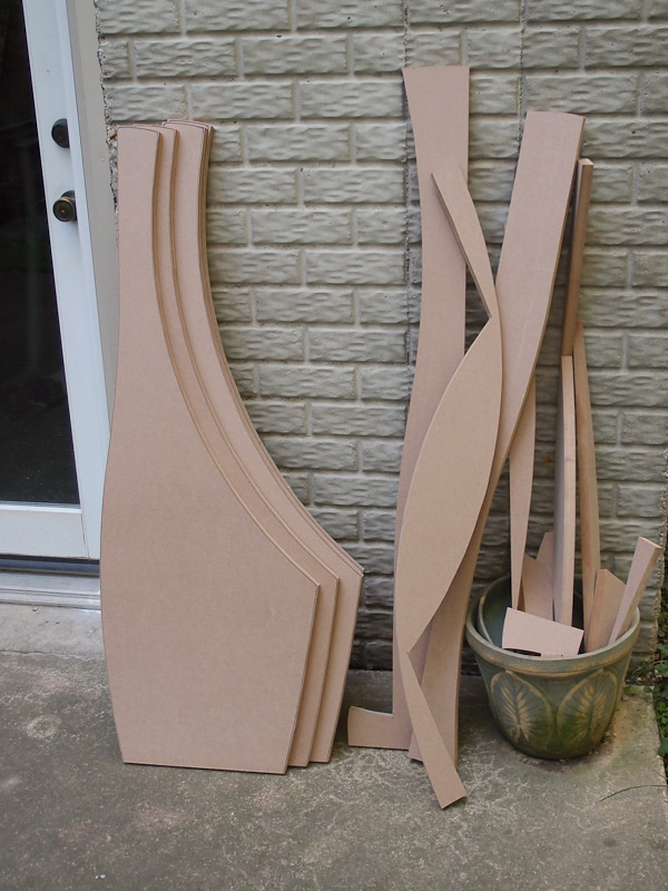
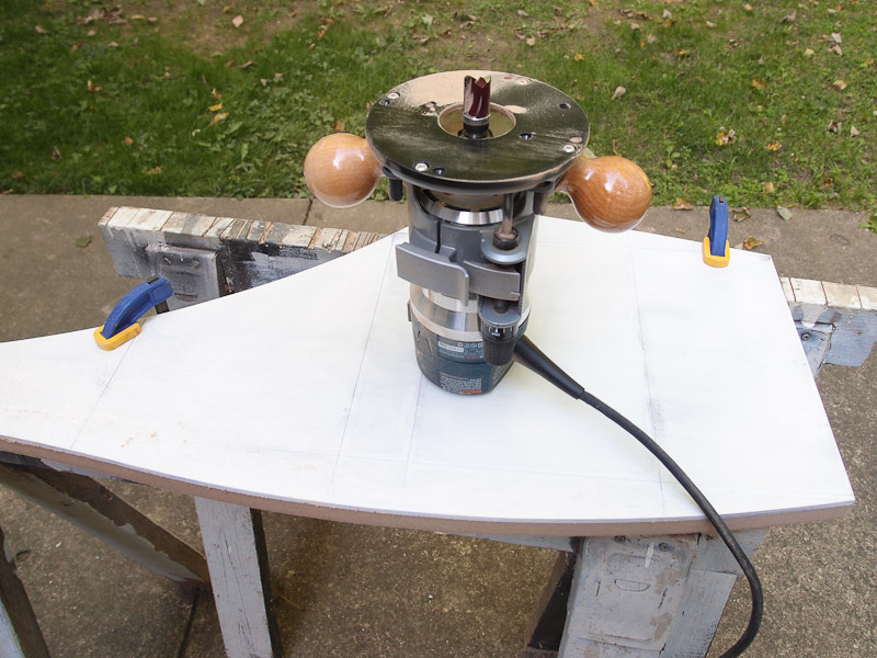
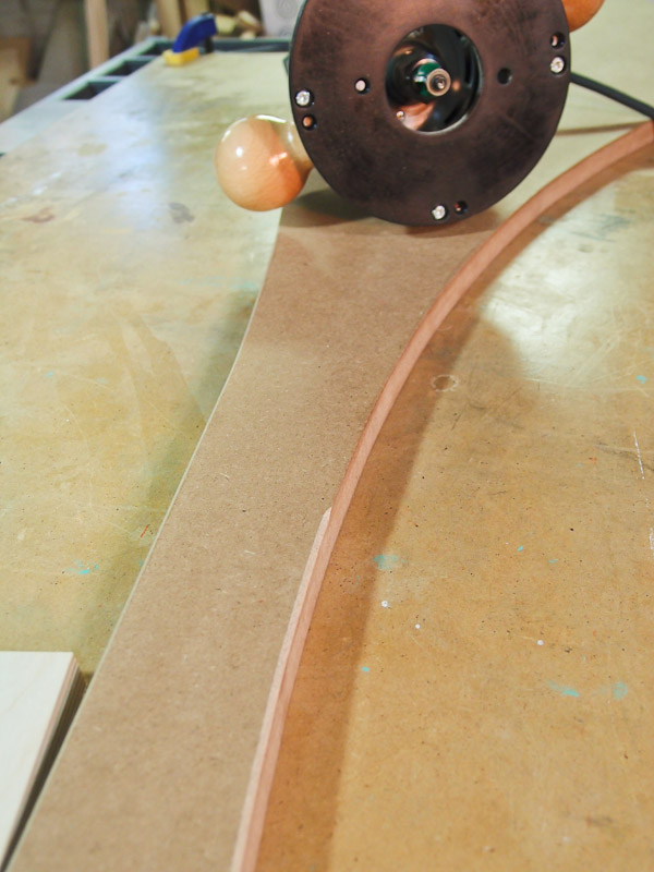
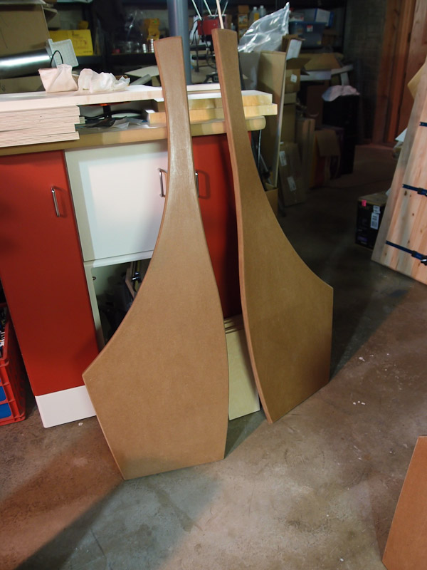
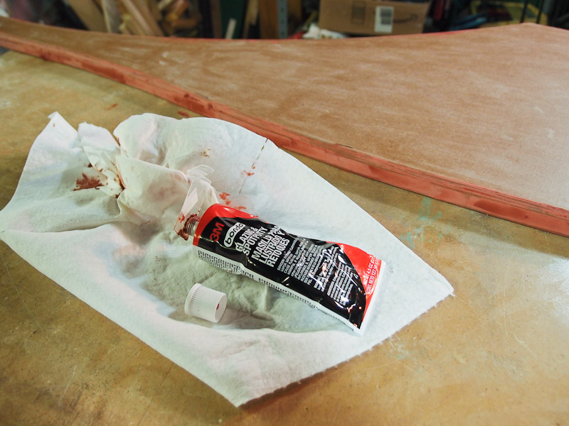
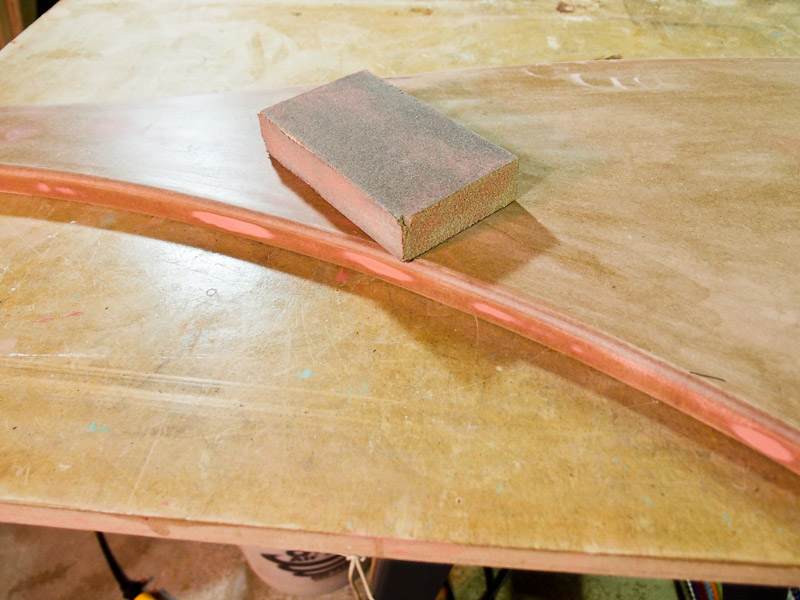
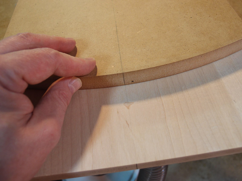
Side Panel fabrication I had intended to do solid wood side panels, but quickly determined that I didn't have enough maple to do the job. I decided to do a set of MDF side panels as a kind of "practice" before I cut into expensive hardwoods. I have a little experience painting MDF because of some previous speaker builds, so that became my fallback position for now. I'll probably redo the side panels in hardwood in a rebuild. I used the side panel template to roughly mark the shape onto a couple sheets of MDF. Outdoors (because MDF sawdust is very fine and gets everywhere), I rough cut the drawn shapes, but left a little material at the edge to be routed away. The rough cutting goes very fast. After rough cutting, I clamped the template to the MDF, and used a pattern bit with a ball bearing to follow the template. This trimming pass puts a very respectable edge to the MDF that needs just a little touch up later on. As you might imagine, the clamps had to be repositioned a couple times to complete the trim. I also discovered that using BIN shellac based primer on the template edge was a bad idea. It tended to ball-up a bit when the router bearing passed over it, and left a cut that was a little rougher than possible. Live and learn. I also should have made a template from thicker MDF using the first template as a guide. It wouldn't take long to do, and it would have provided a larger bearing surface for more forgiveness. Nevertheless, this worked just fine for now. The trimmed MDF pieces were brought inside where I used two different roundover bits to soften the cut edge. A 1/8" radius bit was used on the inside (the side facing the drivers), and a larger bit was used on the outside. This was strictly my choice for appearance. Routing always leaves small undulations on edges, and these become more visible with paint - especially glossy. I began sanding the trimmed edges, shellacked them with Zinser Sand and Seal shellac to harden the MDF edges, then used automotive spot putty filler where needed to fill the slight voids in the edge profile. The spot putty applies directly from a tube, dries quickly, and sands easily. They were ready for their first coat of paint. This always highlights any remaining smoothness issues, so I expect to do more putty and sanding work after the first coats. |
|
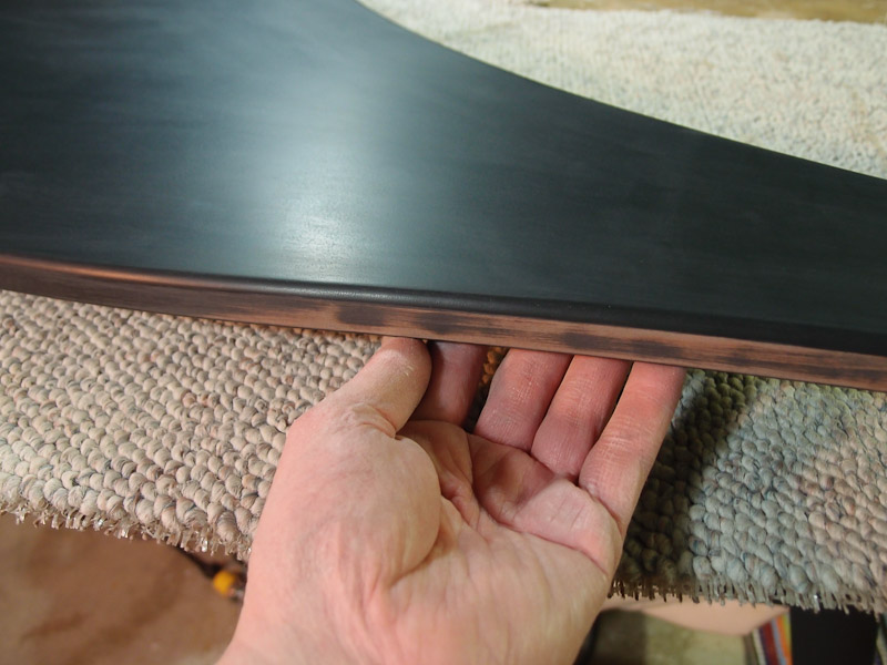
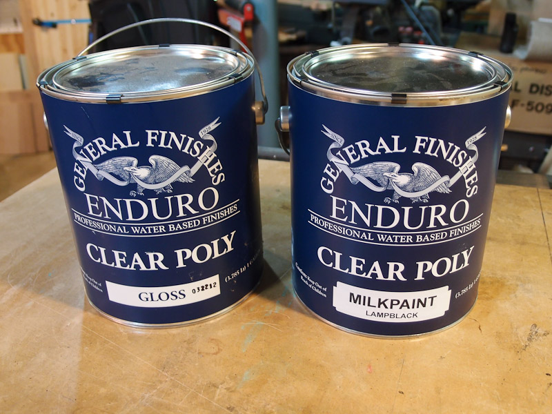
Side Panels - First Paint I used General Finishes Lamp Black paint diluted 1 oz. to 16 oz. of paint for the first coat. It dries to a flat satin sheen. WHen these are completed, I expect to apply several coats of black, then top coat with glossy General Finishes clear acrylic. After applying multiple coats of the glossy top coat, I'll be able to sand into the finish for a nice gloss. At least that's the plan, but it will be a lot of fussy, hard work. Putting a finish on natural wood is much easier. After the first coat, it's back to sanding again. The paint highlights remaining imperfections, and I'm using the paint almost as a sandable primer here. The General Finishes paint sands nicely. Deeper imperfections get a little more spot putty treatment. After a couple cycles of painting and sanding, the smoothness is satisfactory on the flat sides, but I'll work the edges a bit more. I'll set these aside for now. |
|
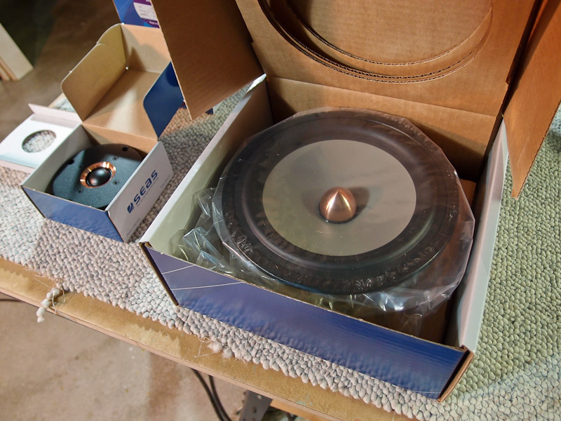
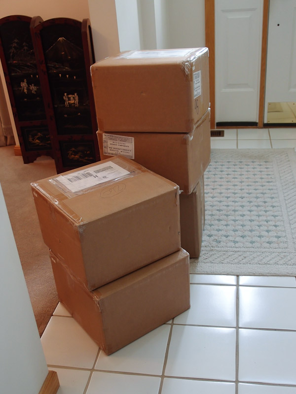
The Drivers Arrive! The drivers were shipped in late autumn 2011. The delay was caused by a shortage of the new SEAS L26RO4Y 10" woofers. It's a new driver designed especially for the Orion, and apparently there were a lot of people awaiting them for purchase or retrofit to existing Orions. The 10" drivers are massive beasts, and weigh more than a typical 10" driver. The midrange and tweeter are very attractive with their copper details. I test fitted the woofer spacer rings and then selected fasteners that I would use for the various drivers. Of course the midrange is rear mounted, so no fasteners will be used for it. I chose #10-24 button head socket screws for the woofers, to be used with locknuts on the back side. Because of their weight and expected dynamics, there have been several advisories to bolt through and use nuts instead of woodscrews. I would not have used woodscrews anyway. The tweeter will get #8-32 flat head socket screws - in basic black, of course. I'll use threaded brass inserts to hold them to the baffle. I may use the standard-issue midrange rear mount kit from Wood Artistry instead of making my own. I like the appearance of that kit, and the price is not unreasonable. Unfortunately the timing of the delivery means that not much will get done on the Orions until next summer (2012). I have to go to work to pay for these expensive drivers, and September through May are my busiest months. |
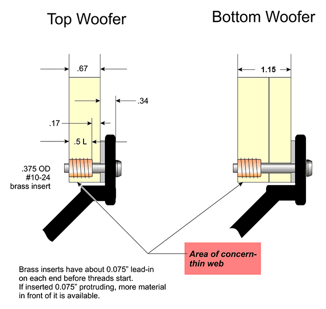 |
I had considered using #10-24 threaded brass inserts in the woofer baffle to avoid using nuts and washers on the back, but when sketched out, the inserts were very close to the woofer through-hole. I was afraid of wood failure where it was thin. |
|
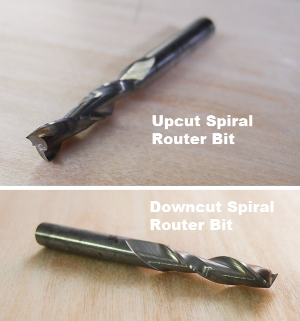
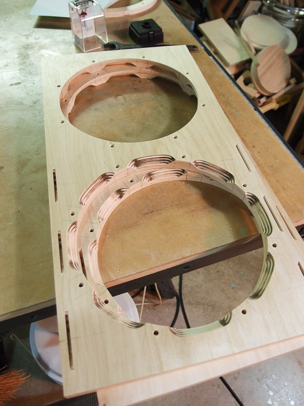
Woofer Box Progress Back to work on this delayed project. After measuring the drivers, I proceed to cut the openings in the woofer baffle. Notice how smooth the plane left the Baltic birch plywood! I'd hate to mess these up now. Guess what happens? The upcut spiral router bit that I've used successfully on MDF projects does not work well with the soft baltic birch plywood. It pulls material from the groove and creates a very rough edge. Thankfully, some sanding took care of most of the problem, but this was not acceptable. I went looking for a solution. The answer was found in a downcut spiral bit. I used it for the first cutting pass (~1/8" deep), then switched to the upcut for the rest of it. Because the backside of the plywood was firmly against a backer board, I knew that the back side would have a clean cut. Besides, the regular upcut coming from behind would pull the grain into the hole - the opposite of what happened when starting the cut - and that worked in my favor. I was left with a very clean edge on both sides for subsequent holes, and any remaining roughness from the initial attempt would be either sanded away or hidden by subsequent work. I learned something new today. That's one of the good things about tackling challenging projects like this. |
|
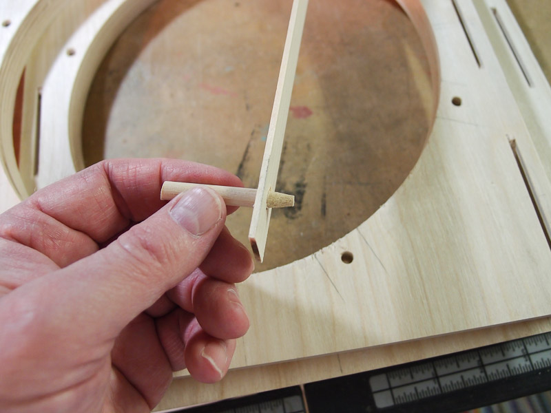
Back Chamfering the Woofer
Holes While Siegfried Linkwitz said that chamfering the rear of the woofer baffle was unnecessary, I decided to do it out of, well..., habit. I marked the locations of the mounting hole lands using a simple device made from a thin piece of table saw cutoff and a piece of dowel rod that I put into the pencil sharpener. When placed in a woofer mounting hole and the stick positioned on the opposite side, it made it easy to pencil-mark the lands evenly. No measuring, no muss, no fuss. Then it's time to go to the router table to put a 45 degree chamfer onto the back of each woofer hole. The pencil marks, brought to the inside edge using a small square, make aligning the stop and start marks for chamfering easy. I got a little burning of the plywood where I paused each cut, but that will be hidden when painted. That's a non-issue here, but something to be watchful of if a natural finish was desired. This operation is a little trickier than most speaker builds because the woofer pairs are mounted in opposite directions, and it would be easy to make a mistake (i.e., cut a chamfer on the wrong side). I just took my time and double checked my progress to ensure I didn't make any mistakes. I made several cuts about 1/16" deep until I was satisfied with the depth of chamfer. Chamfer depth was limited by how much material is left at the side of the hole for the mating baffle piece. You can see in the last photo that I came very close to it judging from the proximity to the biscuit slot. Close is good enough.
|
 |
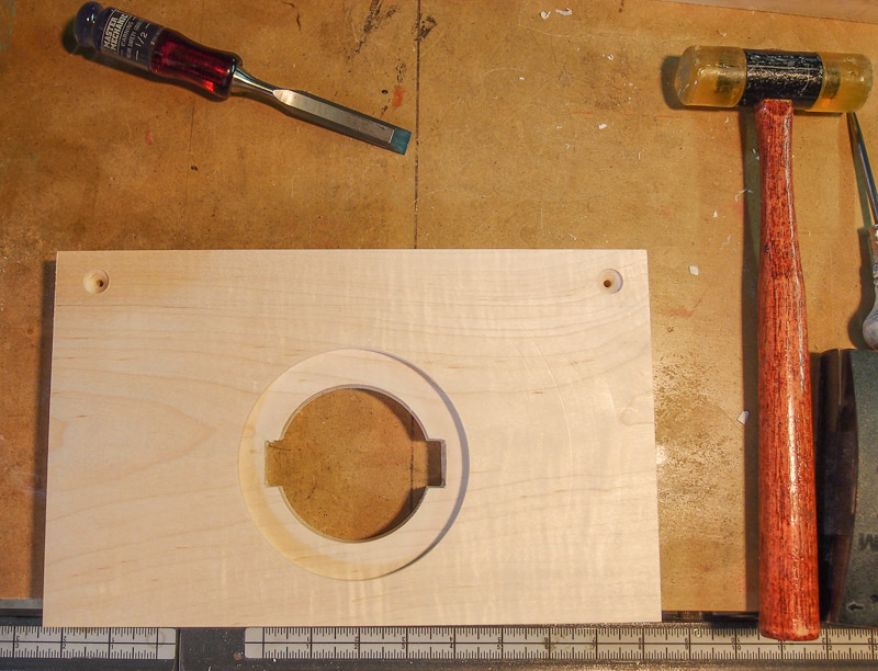
Attaching the Spacer
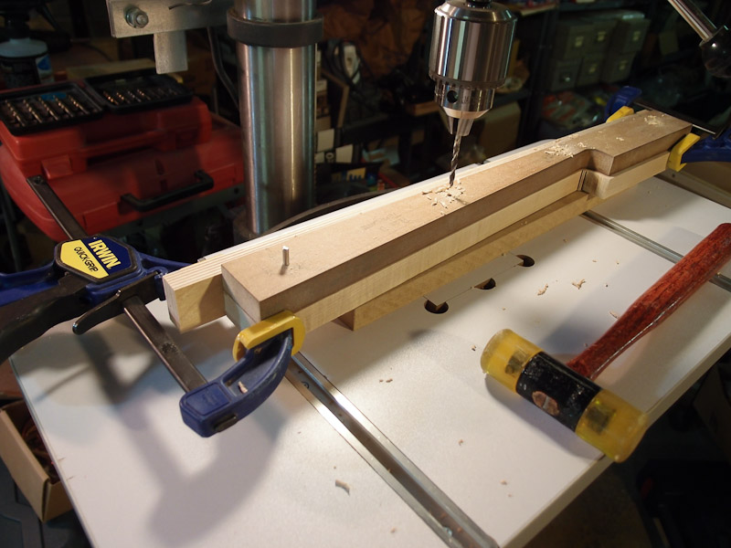
Ring It's time to glue the bottom woofer spacer ring onto the baffle. I used transfer punches to mark the hole locations on the ring (not pictured). The ring was carefully positioned, then clamped with Quick Clamps, and the punch was inserted into each hole and gently tapped with a hammer. This puts a slight indent into the wood to use when drilling. After drilling the holes in the marked locations, I tested progress using real screws to ensure alignment between the two pieces. I had a good fit, so it was time to glue the rings into position. I have a right-angle jig left-over from a darkroom print washer project back in the '80s, and I occasionally use it to hold things upright, as shown at left. I also used in in my Pluto build. It's funny how things made as an expedient earn their keep over the years. After I spread the glue, I used screws through the holes to position the ring where it needed to be. The screws didn't apply much clamping pressure at this point. I used the Quick Clamps to squeeze things together for drying. |
|
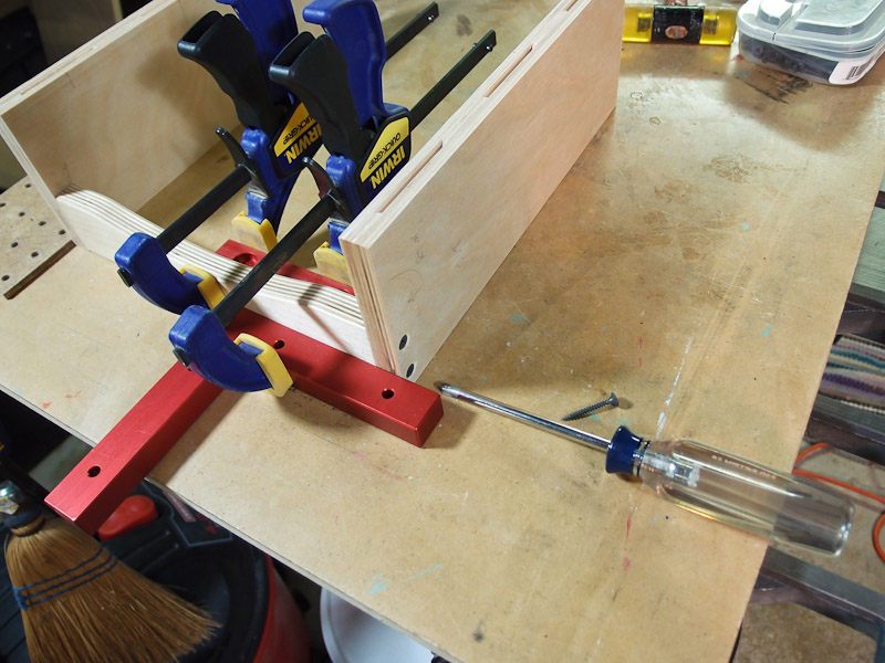
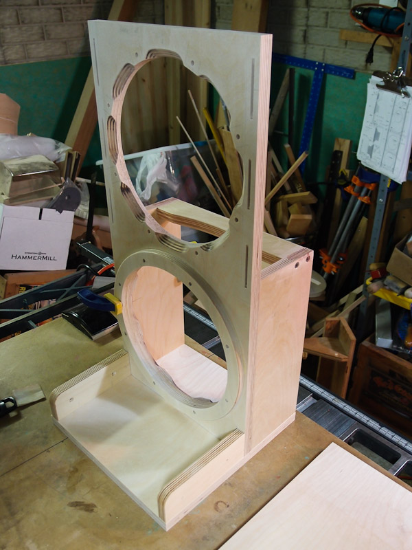
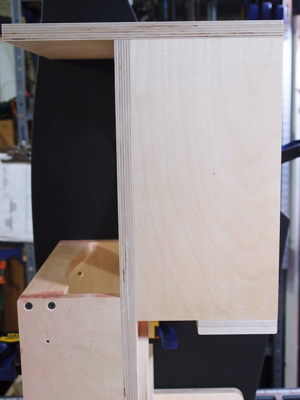
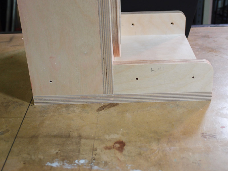
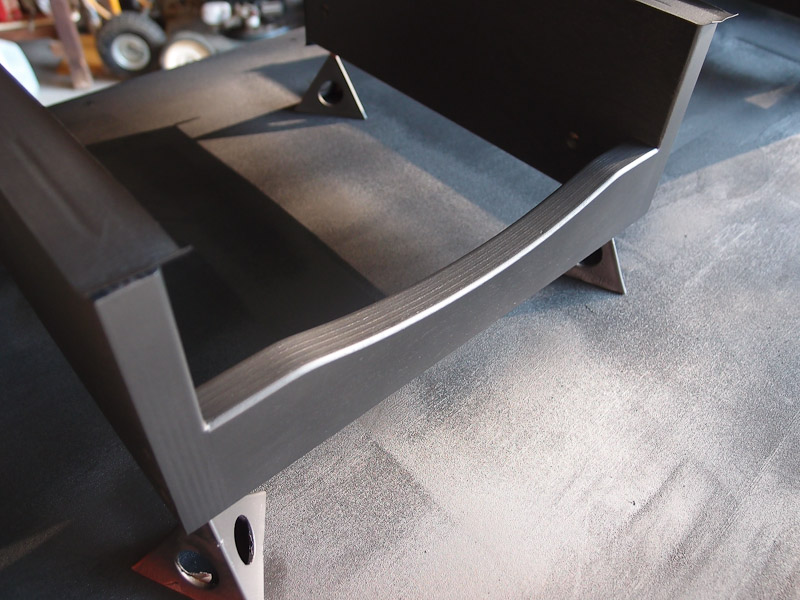
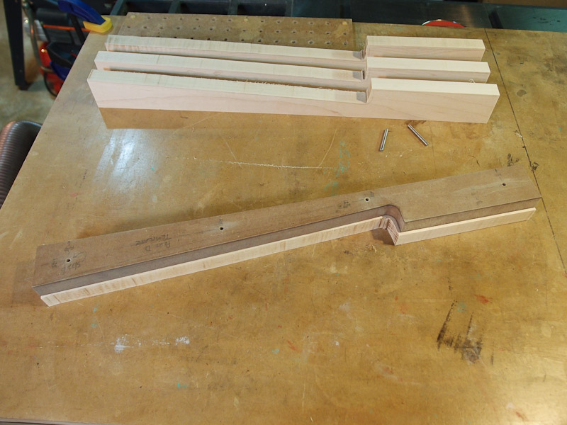
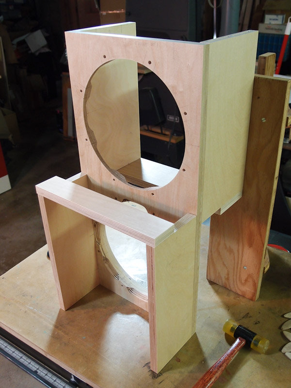
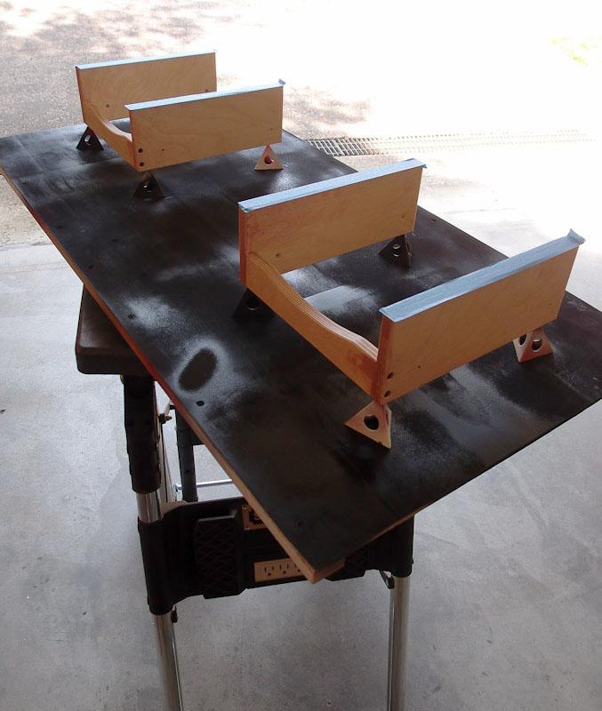
Woofer Box Tweaking After dry fitting one more time with biscuits holding things in position, I looked at the woofer box with an eye toward any small improvements that I could undertake. Two things struck me - one was that the brace for the baffle sides was just sitting on top of the side panels. I looked at photos of completed Orion photos built by Wood Artistry, and saw that it was handled differently. Wood Artistry places the cross brace between the two sides, not straddling it on top. I like this appearance better, but I had already cut biscuits in one of the woofer box assemblies to hold the brace. The biscuit slots would need plugged before painting. Shouldn't be a problem, so I cut the cross brace shorter to fit between the sides and stocked up on putty. Next, it looked blocky. The rest of the Orion is curvaceous, but not the woofer box parts. I decided to cut a gentle 12" radius arc into the back of the cross braces. (Note that this thinking led me to do the same for the upper baffle mount in back too). I simply used a beam compass to mark the curve, took it to the band saw, then used sanding drums on my drill press to smooth out the cut and transition. Easy. I had to carefully mark and drill holes for the screws on both pieces, so they were clamped together for marking using transfer punches. Off to the drill press the braces went for pilot holes. After drilling and countersinking everything, I used a couple of right-angle gluing clamps to ensure alignment of the screws when they were driven home, then took it apart to apply glue, and finally re-screwed things back together for drying. I like this appearance MUCH better than the square blocks. However, a grill will hide all this anyway, so maybe his is all a moot point. It was a good learning exercise however, and that's part of the goal. |
|
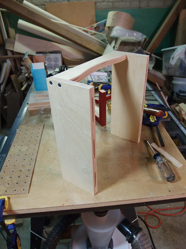
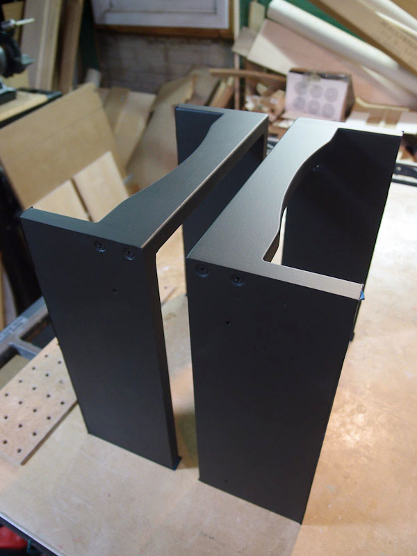
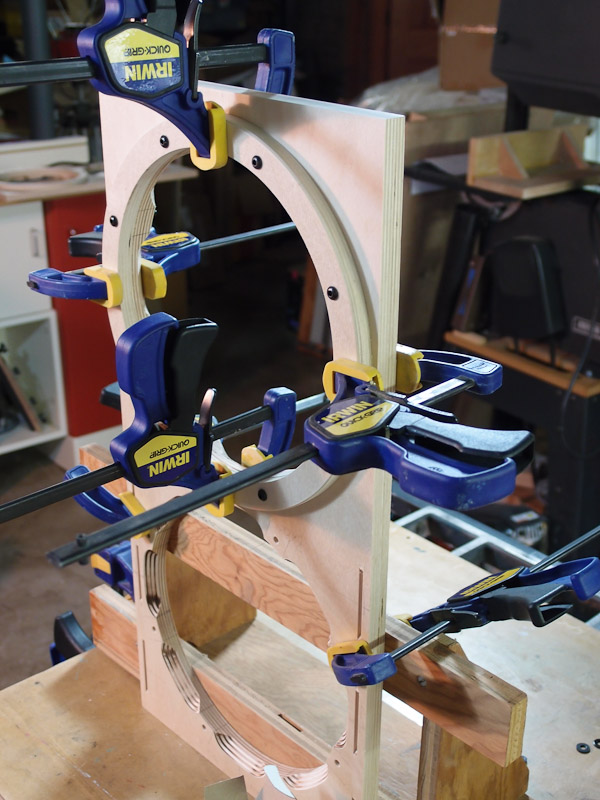
Does the Dry Fitting Ever
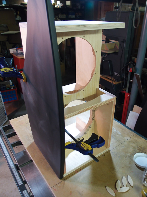
End? Not if you're like me. I make too many mistakes if I rush, so a successful dry fit marks a milestone. It gives me a chance to reflect on what went well, and what didn't. I wanted to get a sense of how the completed Orion would look, so I clamped a side piece into position beside the woofer box. I also checked squareness of cuts and the resulting fit. It looks good to go. I then clamped the other side into position to preview their appearance. |
|
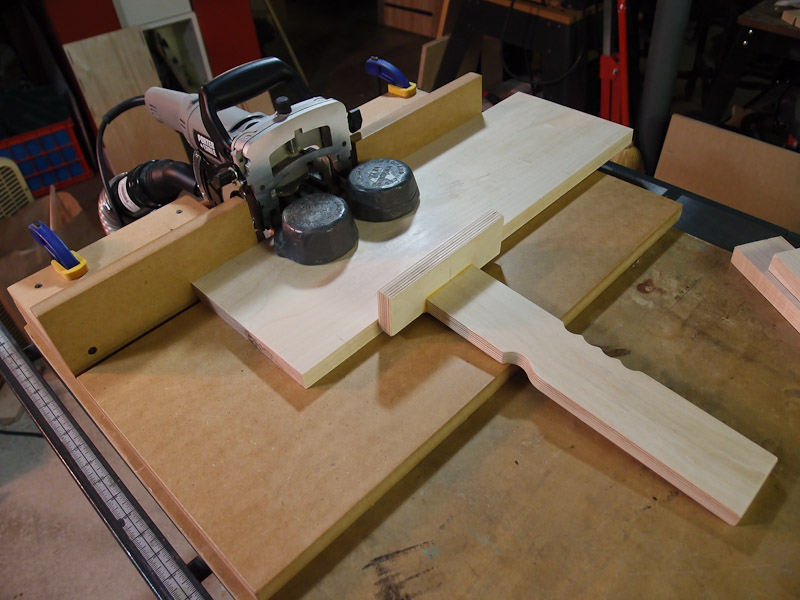
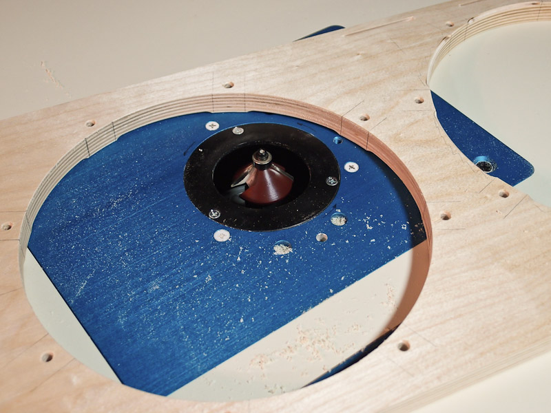
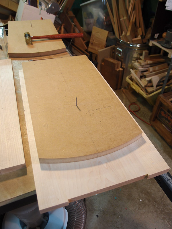
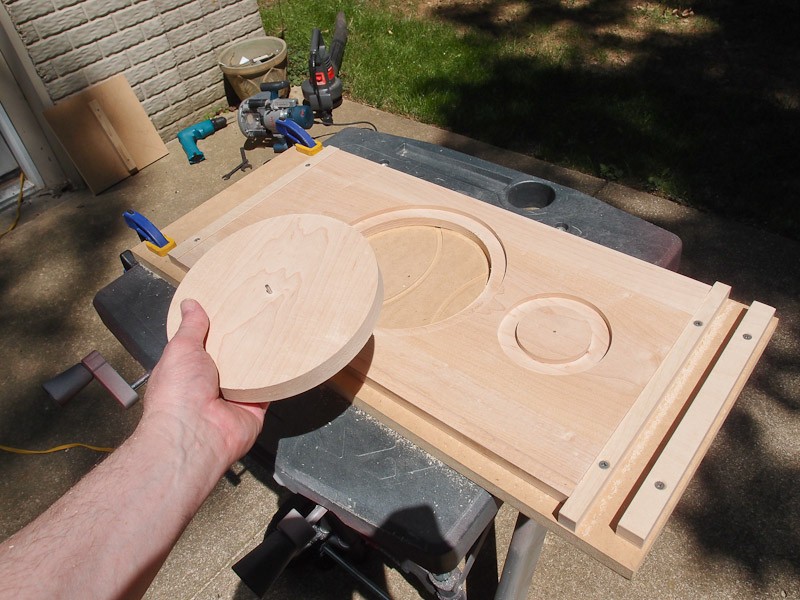
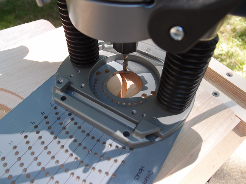
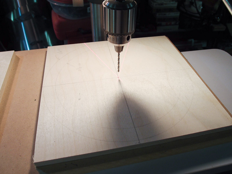
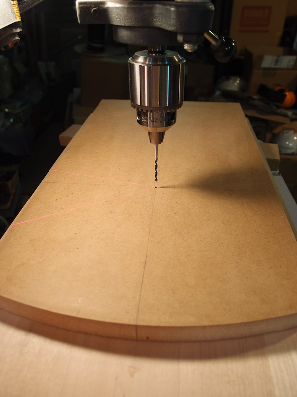
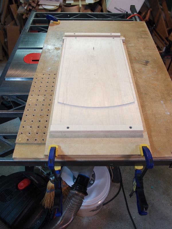
Front Baffle Progress It was time to route the decorative recess around the baffle. I cut two MDF patterns to use on the router table. In a slight deviation from The Plans, I decided to use the tweeter center for cutting the long arc at the bottom. I drilled a 1/8" hole where the tweeter center would be, put in a pin, and swung my router around it (with a circle jig) to clean up the initial band sawed edge. I measured and carefully drilled the midrange hole for a pin also. I used the first pattern to mark the location of the driver hole pins in the second pattern so that they would exactly match. Then I gave them a coat of shellac to harden the edges. Carefully measuring down the center line drawn on the baffle, I drilled one hole for one of the pins in the baffle. The pattern was positioned on top, and a pin was inserted to locate the two pieces. I swung the MDF pattern to align the center lines I had drawn on both pieces, then drilled through the pattern into the baffle to exactly line things up. This went well. Once I was done, I had two patterns on two baffles, located with pins in both the tweeter holes and in the midrange holes. They couldn't slip out of position for the routing steps that follow. |
|
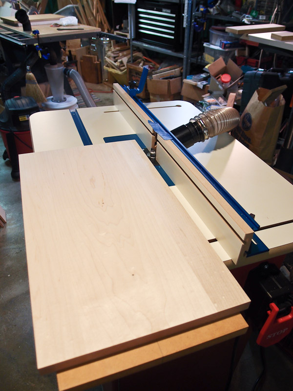
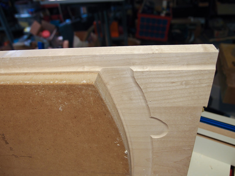
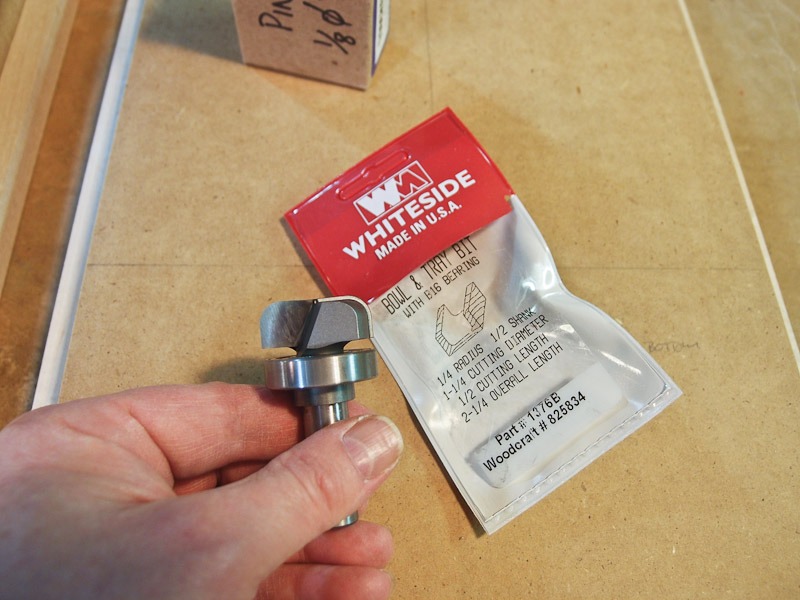
Routing the Baffle
Decorative Relief The decorative relief in the baffle was once done with two pieces assembled together. Many builders took another path making the baffle from one piece of wood with the relief routed in. I chose the latter. I found a Whiteside router bit with a bottom bearing that seemed ideal for this work. It was a Bowl and Tray bit that I purchased from Woodcraft (Part #1376B, Woodcraft sku 825834). With the bit set fairly low for ~1/16" cut, I placed the pinned baffle/pattern "sandwich" face down on the router table. The pattern prevented cutting into unwanted areas on the baffle, and the result was astonishingly good. I took several light passes to reach a final depth of only about 0.150". I left a little more "meat" on the baffle to leave room for cutting biscuit slots on the back of it. The middle picture in this group shows the cutting partway through. There was a little cleanup at the bottom where several overlapping passes back and forth were made. The sides were near perfect. I used a smoothing plane where I could, then switched to card scrapers to smooth out the slightly uneven pass marks. The nice thing about this method is that the pin holes for routing driver openings were already in place. They served a couple of purposes here. |
|
More Painting The woofer box isn't assembled yet (I'm now awaiting the rear woofer mount bracket kit from Wood Artistry), so I decided to paint some of the subassemblies to ease painting later. The first woofer box subassembly to be painted was the front part. I taped off the edges where glue will go later, and painted it with General Finishes Lamp Black water-based paint. After the first coat dried, I could see areas that needed a little spot putty or gentle sanding to maximize smoothness. The end result is very attractive so far. I am unsure of subsequent coatings for the finished woofer box, but I'll probably try a clear satin acylic for protection. This paint is fairly soft, and even the backside of a fingernail leaves a mark on the surface. Without some sort of overcoat, I predict that the black paint would look fairly shabby after a while. |
|
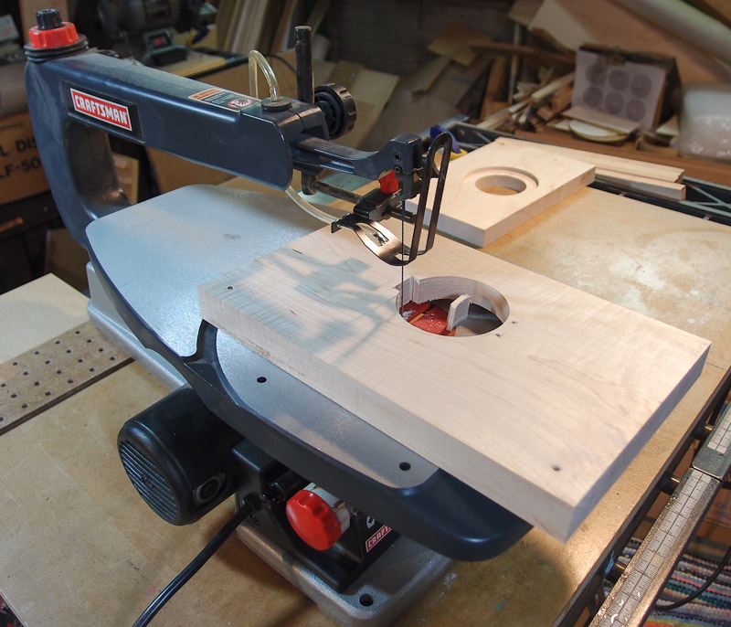
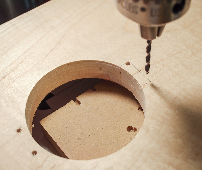
Cutting Driver Recesses in
the Baffle -or- On the Verge of a Bad Mistake The maple baffles were prepared for routing the recesses for the driver flange and through holes. I made an MDF backer board with a way to trap the baffle so it can't move when the last cut detaches the pinned center from the rest of it. The tweeter recesses were cut without incident, and measurements indicate a nice fit when assembled. Wish I could say the same for the woofer recesses. I had mis-measured the OD of the woofers. It was a stupid, stupid mistake - and I did it twice some months apart with the same error! Did I say stupid? I cut the recess too large in diameter (8.875") , leaving a large gap (about 0.075" all around) between the driver and the edge of the recess. However when this was discussed on the Orion/Pluto board, experts said that the gap was appropriate for the rear mounting technique. It gives the woofer a little room to shift around without contacting the edge. Go figure. I'll experiment a bit with some thin felt strips around the edges to hide the gap while minimizing hard contact. The gap is unsightly compared to what is usually seen in normal speaker-building practice. I stopped work on the baffles at this point and shifted priorities to another aspect of the project. Call it a cooling off period. |
|
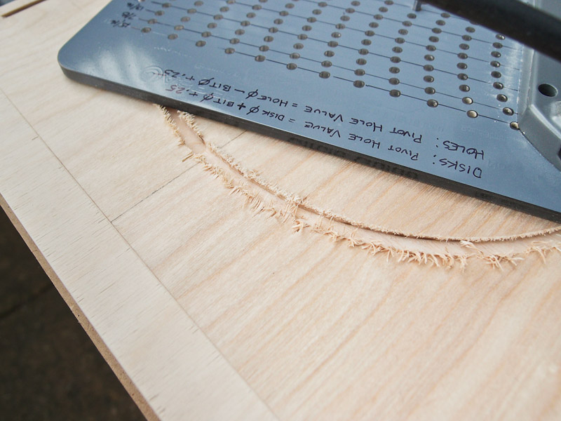
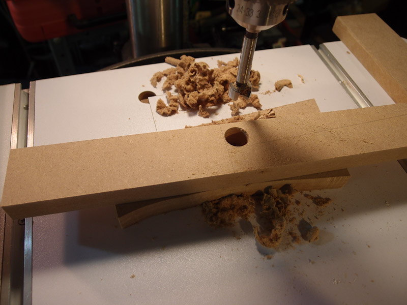
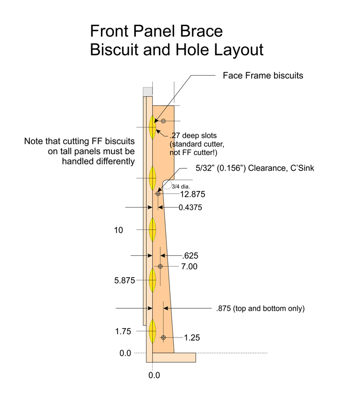
The Plans called for a
simpler bracket to mount the baffle to the side panels. I thought about
how to make it a little better looking. I shaped it to contain the spacer needed for the rear tweeter and to decorate it a bit. (Note that the illustration here has some critical dimensions removed for intellectual property reasons. It would be too easy to reverse engineer if I had left them in.) I had to plan this out to avoid "collisions" between the biscuits and the screw mounting holes. Also, I need to use smaller Face Frame (FF) biscuits because of the thinned cross section of the front baffle. A regular #10 would come very close to protruding from the front. Can't have that. The biscuit cutting jig that I use prevents me from cutting FF biscuit slots on vertical panels. The motor head sticks out further than the cutter. I could get around that by dismounting the cutter from the jig, and use it handheld, but precision would be reduced. Can't have that. My solution is to reduce the cutting depth of the larger cutter wheel to a little over what the FF biscuit needs, and the only drawback would be that the biscuit slot is longer than it needs to be. I can live with that. After planning this piece, I made an MDF template to use for cutting nearly identical copies of its shape and mounting hole pattern. I began by drilling a 3/4" diameter hole where I had penciled in the fillet. Then I took it to a taper jig on the table saw to cut the angled bottom accurately. A little sanding and drilling the mounting hole pattern in it finished the jig. Oh, yes, I gave it a coat of shellac to harden the MDF. I traced around it onto maple boards so that I could rough-cut it on my band saw. Then I took the rough cut maple parts to the drill press to accurately reproduce the mounting hole pattern. I first drilled one hole with both parts registered against a makeshift fence. Then I used 5/32" pins that fit the 5/32" screw clearance holes (for #6 deck screws) to firmly pin the two parts together for drilling the remaining holes. It's probably unnecessary precision, but why settle? The pins were then place in each of the four mounting holes to hold the pattern and the work together for routing the outside shape. I was going to use just two pins at first, but found that the thin section in the middle of the parts allowed some flex. Pinned, they were not going to flex (precision, right?) The router table made short work of copying the outside shape to the maple pieces. The flat back side needed no routing because that was registered earlier when drilling the mounting holes. It was straightforward work, and produced good results. We'll see about the aesthetics when all is finished. |
|
Routing Driver Holes, Part
II I decided to route the through holes for the tweeters and midrange outdoors to reduce dust. It's always messy, but outdoors I can use a leaf blower to disperse the sawdust. I reused an older backing board from my Pluto+ subwoofer project. It is made of a piece of MDF with a 2x2 mounted underneath that I use to clamp to. That is shown in the top picture showing the rear tweeter baffle. The rear tweeter baffle is oversized, and I drove screws though the area to be removed later into the MDF. This keeps the work from coming loose once the router bit cuts through on the last pass. The tweeters got a 4.375" dia. recess x 0.29 deep (to account for a gasket I'll use later), and a through hole of 3" diameter. The midrange holes were cut 7.50" diameter through. The recesses, also 0.29 deep, were cut earlier (see appropriate section above). Notice that I had a curious visitor in the backyard in the second photo. This little fawn is a regular to the backyard, and she was expecting a little free corn. I obliged and went inside to wait for her to finish and leave. One problem I had was that the circle jig embossed some tracks fairly deeply into the smooth maple surface. I expected a little, but not as much as I encountered. I had smoothed the bottom of the jig with sandpaper before starting, and even chamfered the larger holes a bit, but I still got it. I believe that it was because of trapped sawdust particles and that I must press downward with too much force while traveling. I'll try the "small touch-up brush with water" trick to see if the tracks swell up a bit after wetting. Then I'll sand/plane some more to make the surfaces smooth again. |
|
Cutting Recesses for the
Tweeter Terminals I sometimes sweat this step, especially for an open baffle speaker where the workmanship shows. If a tweeter has a compact set of terminals, I merely run a Forstner bit into the baffle to make room. Round is OK there, and it's easy. The SEAS tweeter used here has an elongated terminal block and requires a longer slot. I began by marking out the shape of the recess in the baffles, drilling at the corners, then using a scroll saw to cut the openings. The 1/8" dilled holes are large enough to allow the thin saw blade to turn 90 degrees for the next cut. This method doesn't provide the clean cut that I desire. First, a scroll saw isn't meant to saw through thick hardwood, and the blade tilted a bit to the side. This required cleaning up of the recess with a chisel, which is also not ideal. The workmanship is mostly hidden because of having two tweeters back-to-back in a tight area, but I'd like to find a better way. By the way, the top 1" strip on the tweeter baffle will be cut away later. I'm leaving it on for now to serve as an anti-chip backer board for routing/thinning the baffle in a later step.
|
|
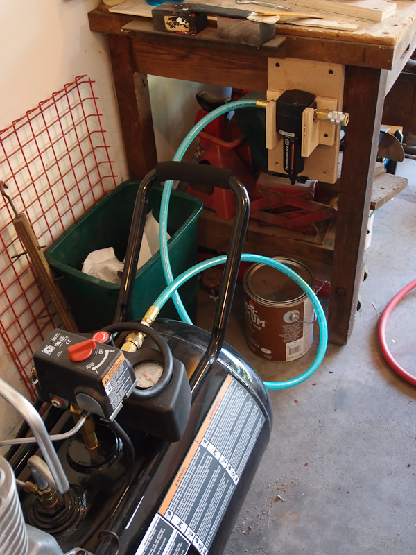
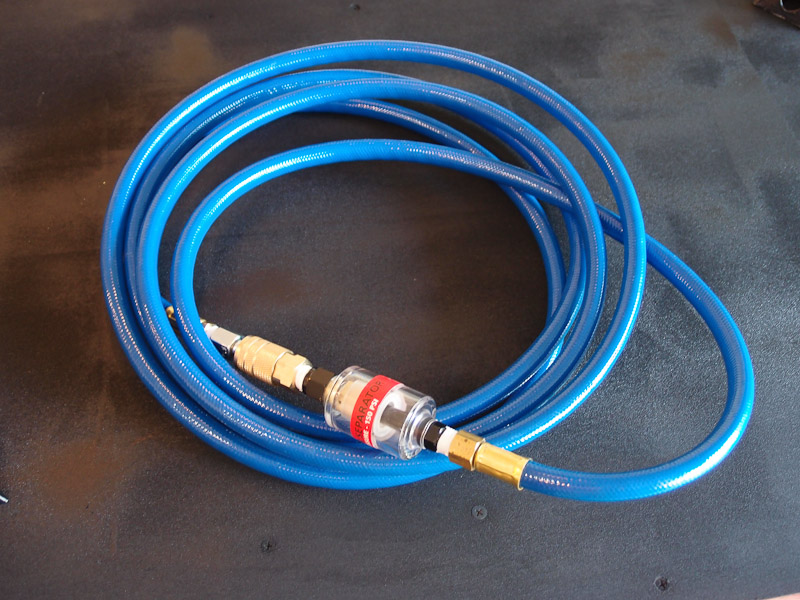
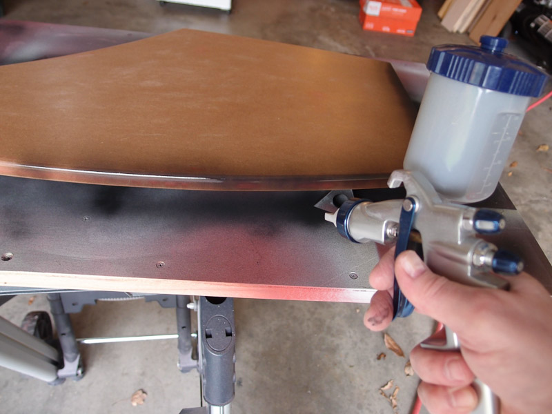
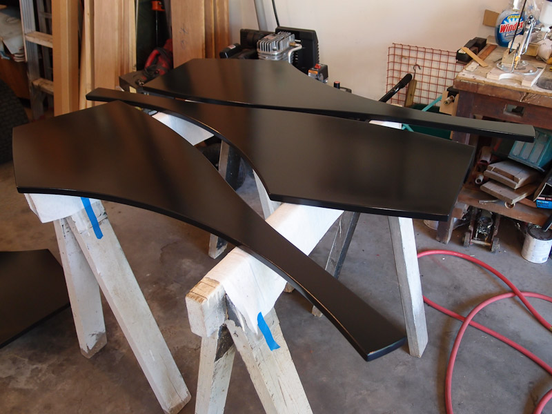
Painting Issues I've been attempting to put clear gloss coats (using General Finishes Polyacrylic Gloss - water-based) onto the side panels, but have run into a couple of problems. First, I'm getting lots of fisheyes in the finish. Usually this is due to moisture in the air line when using solvent-based finishes, so I assume that the problem is oil with my water based finishes. I have a Norgren oil/water filter between the compressor and spray gun and I still have the problem, so I must have contaminated my air hose somehow. I purchased a new air hose and an inline filter to use at the gun. I haven't tried it out yet. The second issue may be spray-gun related. I can't see to get an even overlapping spray pattern on each painting pass. This puts "stripes" of different gloss on the surface. My gun is a very cheap Lowe's detail gun, and I might be asking too much of it for larger panels like these. I'm on the lookout for a new gun to use with water-based finishes. One other thing - the "painter's pyramids" that I used to support the panels during painting leave a small dent in the finish if a panel were left sitting on it. That included the clear finish that was days old and should have been completely dry. Sigh. More fixing to do later. Yeah, I know, blame the equipment! More painting work is needed when I get the time. These are set aside once again. |
|
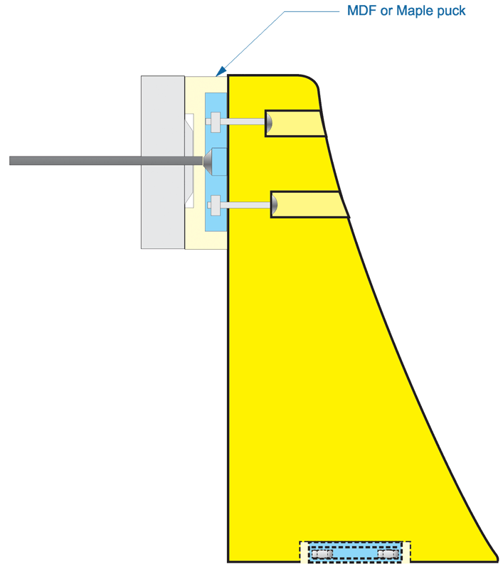
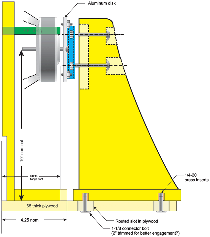
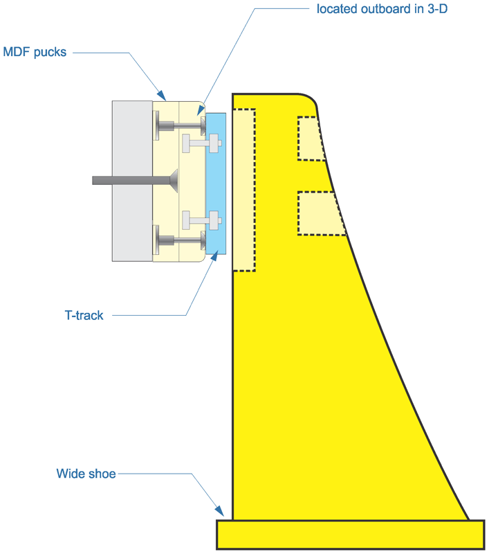
Rear Mounting Schemes
for the Midrange Driver One of the distinctive features of the Orion loudspeaker is that the midrange driver is mounted by its magnet at the rear. This removes vibration from the front panel. I considered several ways to accomplish this task. The method chosen must accommodate several degrees of adjustment. In some of my sketches, I also considered making a foot for the upright brace made from wood, but with a relief routed in its underside to hold some 1/8" felt. I reasoned that felt would damp vibrations that get passed through the upright before they could reach the top of the woofer frame. Some of these approaches would require a little metalworking in addition to woodworking, especially the last one that employed a circular aluminum plate. Small adjustment screws would protrude toward the driver to press against the magnet assembly in order to get some additional adjustment - pitch and yaw. I had envisioned some t-track in each of the concepts for adjustment.
Eventually I just purchased the Wood Artistry kit to save time. The cost is very reasonable for what you get. |
|
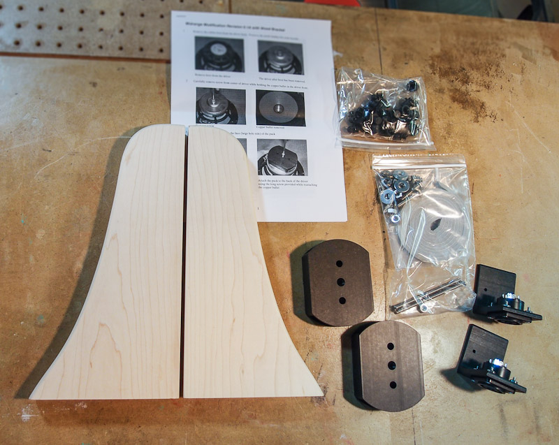
Wood Artistry
Parts for Orion As mentioned just above, I just contacted Wood Artistry and purchased the midrange mounting kit for Orion. I figured that I would spend way too much time reinventing the wheel, and that WA's price is very reasonable for what you get. I also purchased the Speakon terminals with black anodized aluminum brackets, and plastic grill mounts while I was at it. I was pleased to find that a set of black plastic plugs for the midrange's screw mounting holes were included in the rear mount kit. Nice touch! One of the maple mounting brackets had some minor "bruising" courtesy of the post office. I suspect that the aluminum brackets for the Speakons dug into the wood during shipping. A common trick to remove minor dents from the surface of unfinished wood is to apply a drop of water to the dent, and the wood expands a bit. In my case, it was very good after the water treatment but still visible, but a final pass with my smoothing plane removed any traces of the damage. |
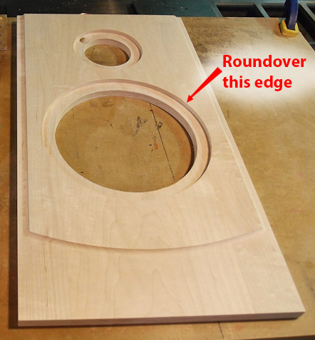 |
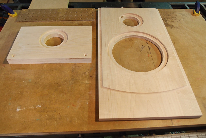
Rounding
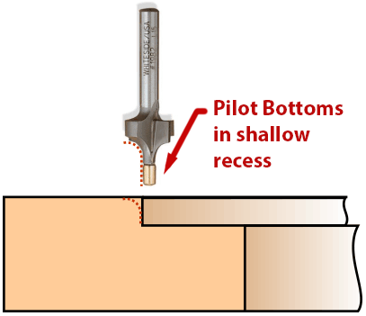
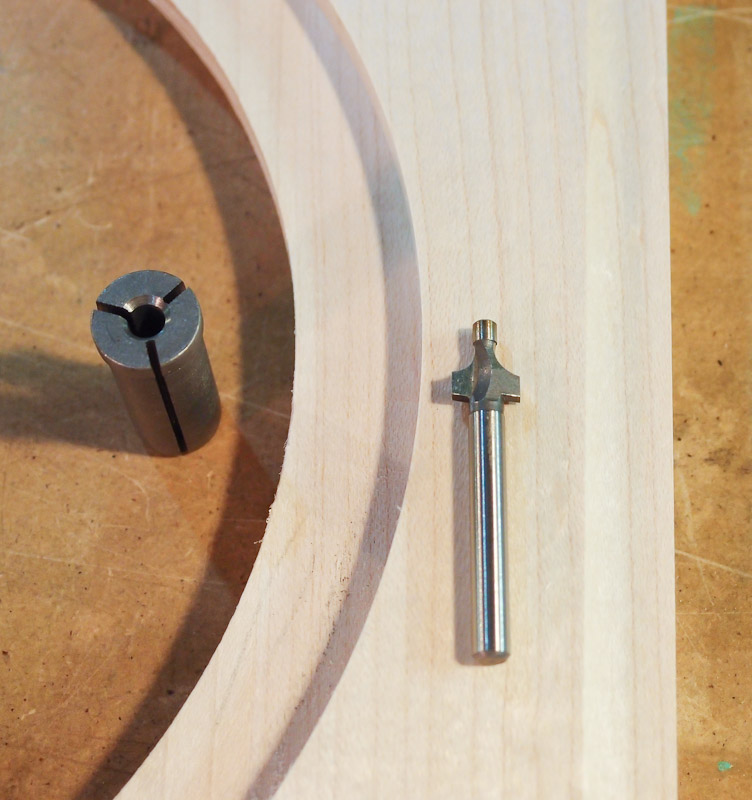
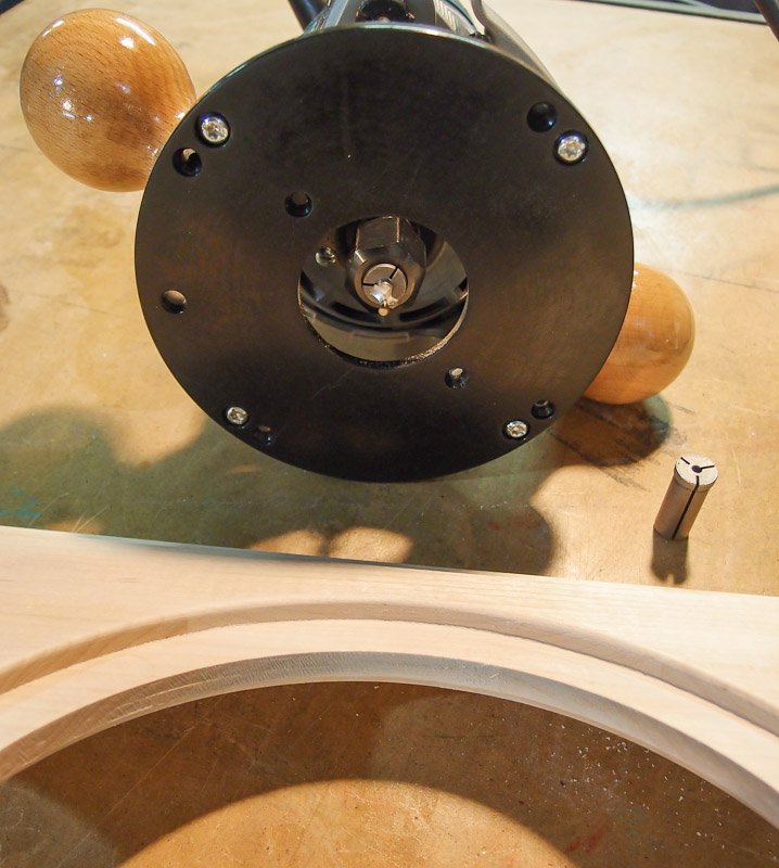
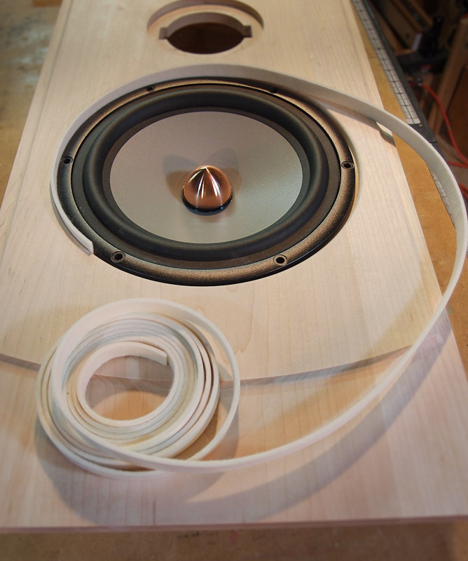
Over the Midrange Recess Edge Because the woofer rebate diameter is large due to "slop" needed for rear-mounting the midrange, it looked a bit untidy compared to the usual tight fit around a typical speaker driver. A hard, sharply cut edge didn't quite look right with a lot of space showing around the driver. I went looking for a way to round over the edge of the cutout. My first inclination was to reach for a roundover bit for use in my router or router table. I quickly discovered that typical bearing-equipped roundover bits were way too long to fit the shallow rebate, and even a petite Whiteside 1/8" roundover bit with a brass pilot was too long. These roundover bits bottomed in the recess before the cutter made contact with the edge. I managed to find a very small 1/8" radius roundover bit (~$14) meant for a Dremel "Trio" tool at Lowe's that came close to fitting the recess, but it had an odd 3/16" diameter shaft. That doesn't mount in any "real" router that I know of. Online, I found a company called Carbide Processors that sold a 1/2" to 3/16" router collett reducer for about $13. I ordered one to be able to chuck the small Dremel bit into my Bosch router. I also purchased their 1/2" to 1/8" reducer in case I ever needed to mount an even smaller bit someday.I still had to grind the pilot of the Dremel roundover bit shorter so that it could fit into the recess without bottoming. That didn't leave much pilot length remaining, but it worked fine. I want to be able to put some felt around the periphery of the driver to prevent the basket edge from contacting the side of the baffle. I ordered some 1/16" thick F1 white felt strip from McMaster Carr (5051K422) in order to try this. It needs trimmed to fit the recess depth, and I'm sure that cutting it evenly using a paper cutter will be tricky. Another challenge to be researched! |
 |
|
 |
|
 |
|
 |
|
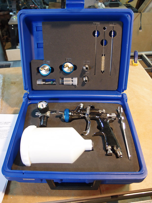 |
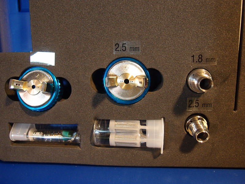
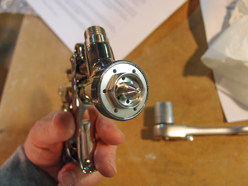
September
2012 - New Spray
Gun and Paint
At the recommendation of an internet acquaintance, I contacted Jeff Jewitt of Homestead Finishing to see about solutions to my spray painting problems. First he gently scolded me for trying to spray finishes meant primarily for brushing (General Finishes Milk Paint Lamp Black, and GF Clear Glossy PolyAcrylic). He also said that the small Lowe's spray gun that I have currently is really designed for automotive finishes, and is not ideal for the heavier water-based finishes that I'm using. Enlightened by this discussion, I purchased a Qualspray AM-5008 "SmartPak" gun kit with several nozzles and other accessories. Jeff recommended using the 1.8mm nozzle option for some paints that he also sold to me. The paints are pricey with the black specially formulated (and they come in large 1-gallon cans), but if this works better than the smaller Lowe's gun and off-the-shelf paints, it will be a good alternative. |
 |
|
 |
|
 |
|
 |
During a break in the project
in October,
I started planning some of the items remaining. One troubling
subassembly is connecting the baffle to the bottom brace. Both parts are
fabricated from hard maple, but the grain runs at right angles. Expansion
and contraction will be significantly different, and that might make
gluing unwise. I'd hate to split a baffle because the humidity changed!
I calculated how much movement is possible in a hard maple baffle of this size, and it was a surprising 0.150" across the width. The bottom brace won't expand nearly as much, putting great stress on the joint if the calculations are true. As a result, I'm considering using pocket hole screws instead of a glued joint. They can move in the bottom brace screw holes to allow for expansion. My only concern with this method is that the front baffle is only 1/2" thick where it meets the brace. Will that be enough thickness for screws? I suspect it might be, especially because of the vertical braces (not shown), and they will attach to the bottom brace also. |
| DILEMMA!
|
The LX521 monitor loudspeaker has been announced by
Siegfried Linkwitz. It has some advantages over the Orion in terms of
acoustic polar response. It uses the same expensive woofers (SEAS L26RO4Y, D1001-04) as the Orion, and I already own them. There are new midrange and tweeter drivers to purchase, but their cost is moderate by comparison. Upon hearing good reports from public showings of the prototype, I bought the LX521 plans and circuit boards. I have begun work on the LX521 Monitor and this will slow/stop work on the Orions. At this point, I'm not sure of the outcome of this work on Orions. |
| [January 21, 2013] From the lack of updates, it must
be obvious to the reader that I have mostly abandoned this project. I
don't know if I will finish Orions when the LX521 is getting such good
reviews. I've refocused my energies on the newer LX521 design. Time will tell whether I return to these, or abandon this project.
|
|

t-800px.jpg)
-800px.jpg)
-800px.jpg)
-800px.jpg)
-800px.jpg)
-800px.jpg)
-800px.jpg)
-800px.jpg)
-800px.jpg)
-800px.jpg)