| |
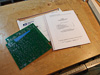 |
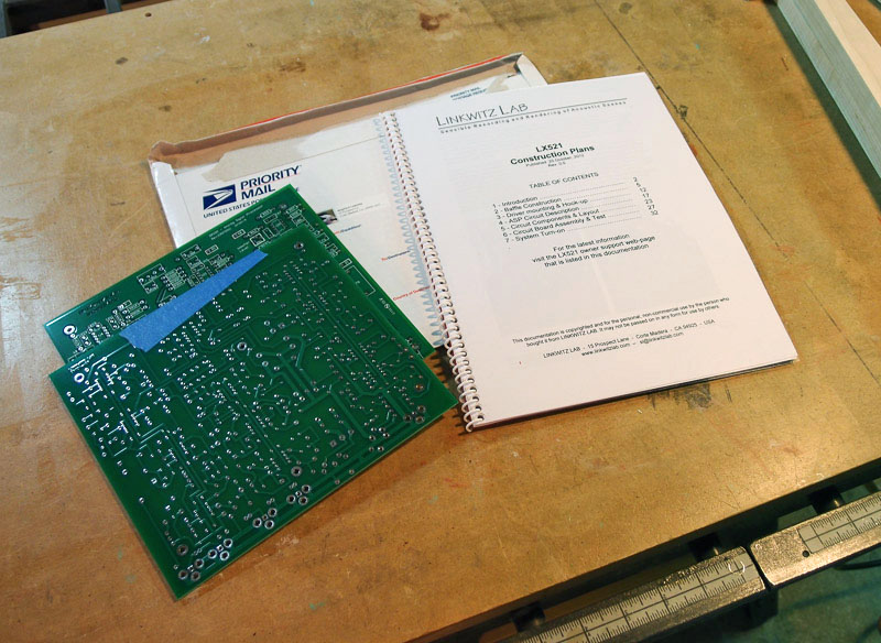
Plans Arrive
[November 20, 2012]
<--click any thumbnail to enlarge
I've ordered the plans and
ASP circuit
boards from
Linkwitz Labs.
They arrive in about a week via Priority Mail.
[NOTE: Linkwitz passed away in September 2018. Plans are not available directly anymore,
but Madisound
and http://www.magiclx521.com
have
taken over distribution of them. Also, newer versions of the LX521 use DSP for the active crossover instead of
ASP analog circuit boards.]
|
| |
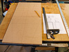 |
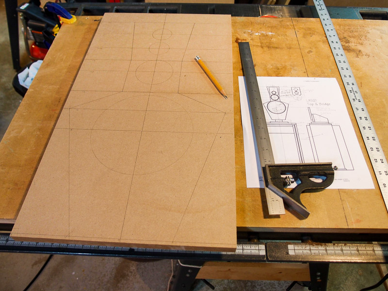
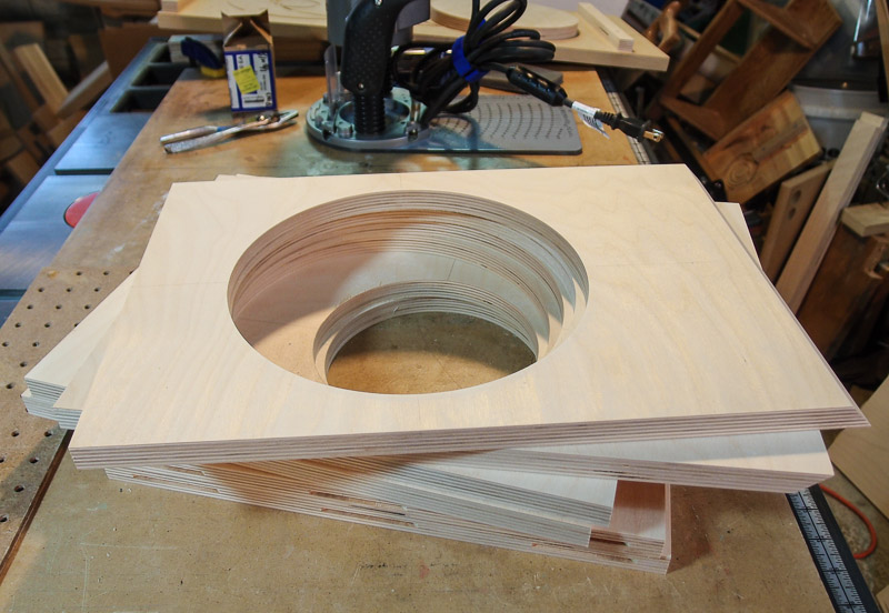
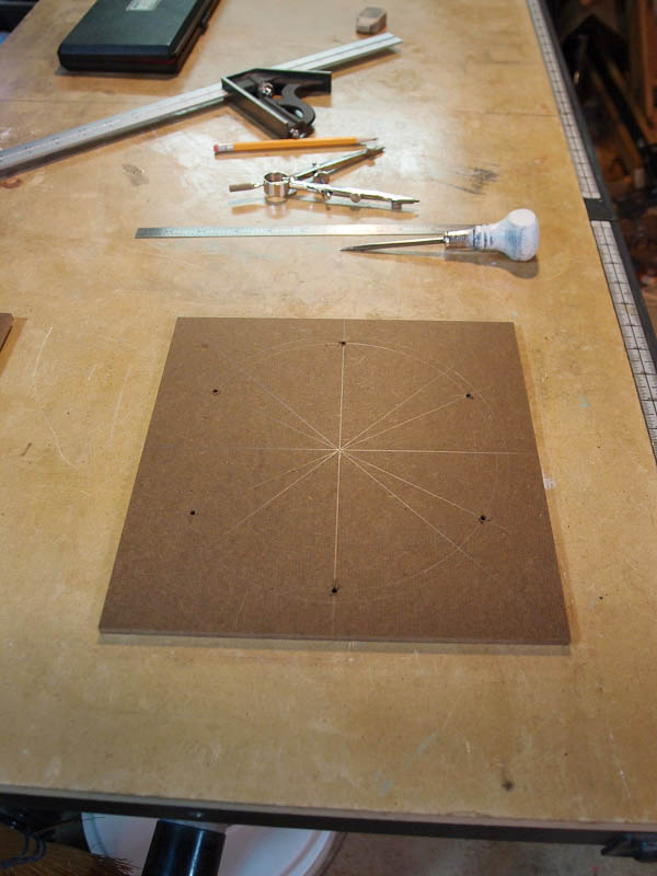
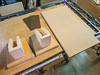
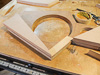
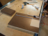
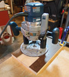
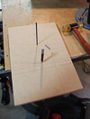
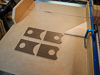
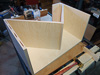
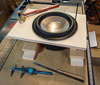
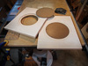
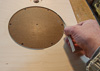
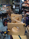
Planning Baffle
Fabrication The photo
shows the baffle layout being sketched on 3/4" MDF. I plan to use this
as a master template for routing subsequent copies. This piece won't be used
on the loudspeaker itself.
The baffle is an unusual shape. The width
of the baffle changes with each driver to make it small acoustically.
Because it is an open baffle loudspeaker, the fabrication of the baffle
should be easier than with a box-type loudspeaker. I'm still exploring
what materials to use (black-painted MDF or plywood, hardwood, etc.).
I've also ordered some unusual size Forstner bits to cut the tweeter
holes and the upper midrange speaker hole. |
| |
 |
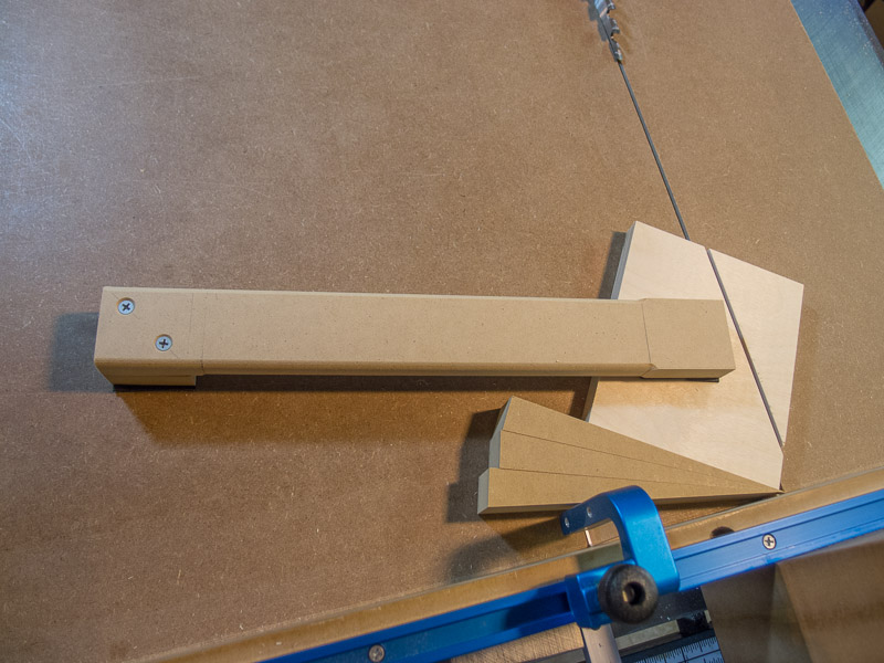
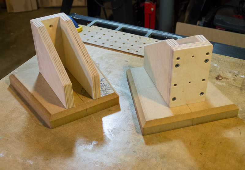
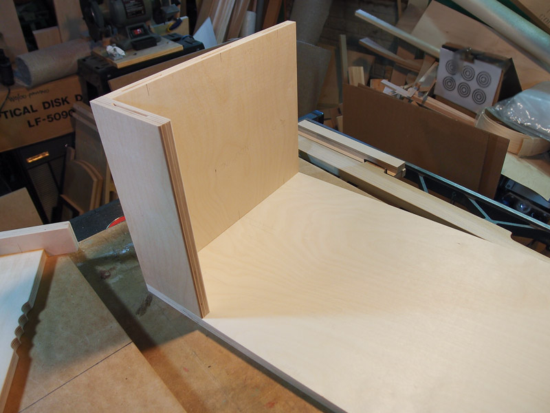
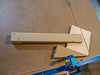
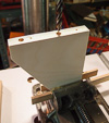
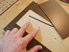
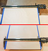
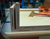
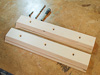
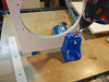
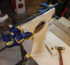
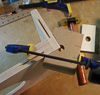
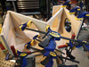
The Baffle Bracket
In the plans, the baffle is held to the structure with a bracket
that I'm making from a combination of 1-1/8" MDF and 18mm Baltic birch plywood.
I used my table saw sled to rough cut the pieces, and also used it to cut the
angles on the brace uprights. You can see the hold-down stick in the first photo
to keep my hands away from the spinning blade. It has a rubber facing on the
side that contacts the work piece.
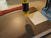
I've already taken some of the parts to the router
table to put on a small 1/8" radius on the edges of the MDF "foot" and the
plywood sides. That should help prevent skinning my knuckles on sharp edges when I'm
working with the passive crossover to be located between the uprights. [Edit:
Later on in this project, I re-routed a much larger chamfer instead of the small
1/8" roundover in order to match the appearance of the rest of the bridge.]
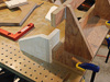
In a slight deviation from plans, I made the brace
"foot" into a trapezoidal shape to echo the angles designed into the baffle. This
brace assembly will be painted black like SL's, probably using Lamp Black
water-based General Finishes Milk Paint. It will be sprayed or rolled-on after a
good shellac coat is done to seal the wood/MDF. |
| |


|
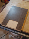
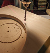
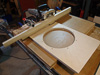
Work continues on the Pattern for the
Baffles [November 30, 2012]
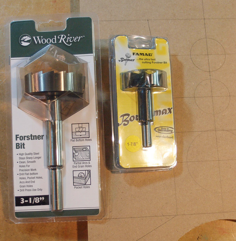
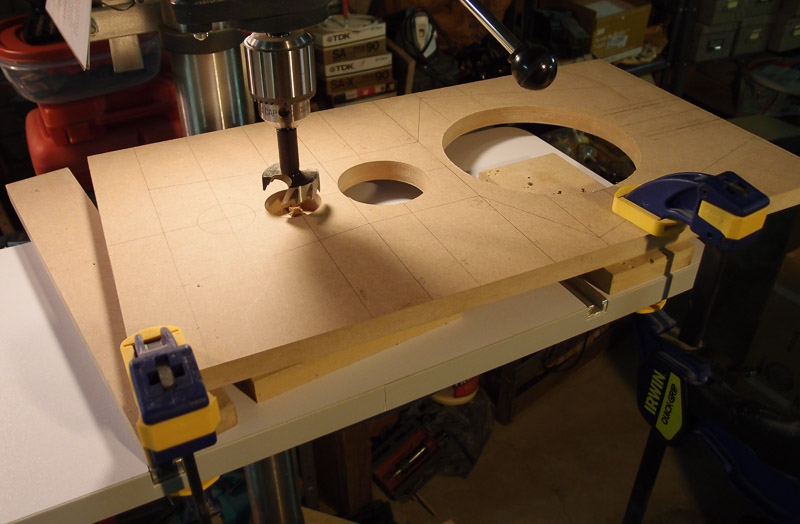
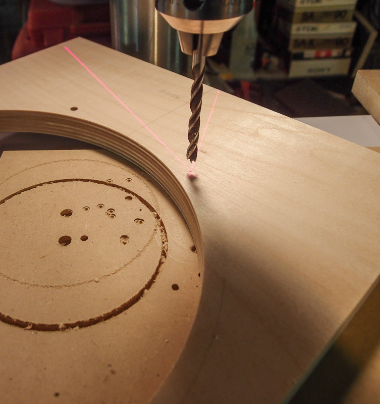
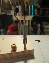
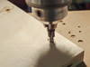
I ordered some Forstner bits from Woodcraft to cut the
upper mid and tweeter holes. I could have done it with the router, but I
dislike the process - especially when the weather is marginal. If I
can't use the router table, I route MDF outdoors because of the dust.
With poor weather outdoors, the Forstners will make life easier.
One Forstner is 1-7/8" in diameter (tweeter) and the
other is 3-1/8" in diameter. The 3-1/8" diameter is slightly too small
for the driver (by about the thickness of a business card), but I used a
sanding drum on my drill press to enlarge the hole in the pattern to the
needed dimension. This enlargement took about 10 minutes with pauses for
measurements along the way.
A 3+ inch Forstner is about the upper limit that my drill
press can swing without straining. I took light cuts, and repeatedly
pulled the cutter from the hole to clear chips and to cool the tool.
I was very pleased with how clean the Forstner bits
worked. Not much dust went airborne - unlike cutting the holes with a router.
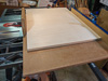
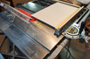
After I cut the holes, I trimmed the overall length of
the baffle on my table saw. The table saw's sled made this very easy.
To cut the outside shape of this irregular baffle, I
took it to my Sears Craftsman band saw. I've improved this hand-me-down band saw over the years
so that it cuts straight and smooth. However I quickly discovered that
the narrow throat of my band saw is too small for the baffle when it was angled for
some cuts. I did as much as I could with the baffle facing up, then
carefully marked the problem cut on the back and cut the rest that way. If
turning it upside down hadn't worked on the band saw, I was prepared to use the jig saw
for any remaining problem cuts. After all, this has to be close to the
line, and not exactly on it. The excess will be trimmed to dimension in
a subsequent step.
I am able to cut fairly close to the mark with the
band saw, but I'm leaving a little extra material to be trimmed off
either with sanding (if there isn't much material left to remove), or on
the router table using a pattern bit after I tack down some scrap pieces
of MDF to use as a temporary guide for the cuts. I eventually went with
the router table approach because it is so straightforward and fast.
This pattern must be well-made. The resulting baffle
copies will echo any flaws it contains. Outside edges must be smooth
and straight. The router bit will ruthlessly expose any sloppiness or
irregularities.
|
| |

 |
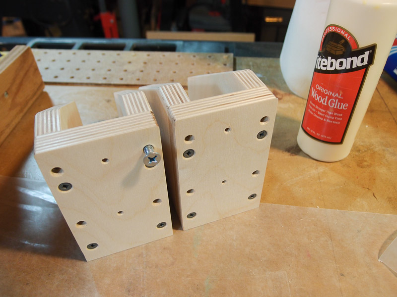
Continuing Work on the Brackets
[December 2, 2012]
With the baffle pattern in its current state, I was able
to mark out the mounting screw hole pattern on the baffle. I drilled
1/8" pilot holes in the baffle, and used transfer punches to mark the
front of the bracket.
I plan to use 1/4"x20 machine screws to hold the
baffle to the bracket so that I can easily interchange baffles. I may
make painted MDf baffles to start with, but later switch to hardwood as
time and materials become available. I like being able to change my
mind.
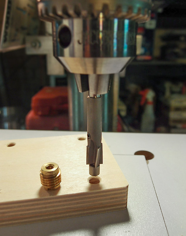
I drilled 1/4" diameter through holes on the bracket
front, and used a 3/8" diameter counterbore with a 1/4" diameter pilot
to have near perfect concentricity. The
changeable-pilot counterbore
tool was purchased at McMaster-Carr a while back, and it works
splendidly. It has interchangeable pilots to align with just about any
size pre-drilled hole.
After creating the 1/2" deep x 3/8" diameter
counterbores, I inserted
1/4"x20 threaded brass inserts into the rear
side of the baffle bracket. That leaves about a 1/8" inch "land" of
material on the front to eliminate the chance of pullout.
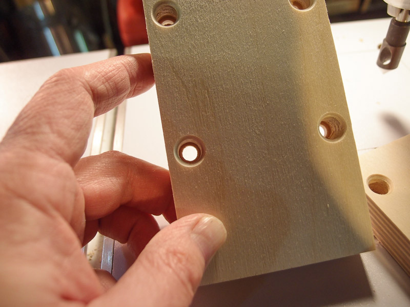
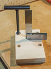
The threaded inserts are installed using a
T-wrench
that I purchased from Woodcraft years ago. I have to use a washer with
it to prevent it from wedging into the back side of the threaded
inserts, but that's easy. While installing the inserts, I keep a small
square handy to judge how straight the insert is going in.
I may use screws that are longer than the thickness of
the baffle bracket and baffle combined, so I bored 5/16" diameter holes
into the edge of the bracket sides. This will permit a fairly long screw
to pass completely through the threaded brass insert and still fit
without bottoming.
I added a couple of small holes on the vertical
centerline of the bracket in case I wanted to mount a hardwood baffle
without any mounting screws visible from the front of the speaker. They
are just "what if" holes just in case. It is easier to drill and
countersink them now than after the bracket is assembled.
Once everything was fitted nicely, I put a thin layer
of glue on the mating surfaces, and tightened the 1-1/4" deck screws
that I used to clamp it together.
Things are nice and square, with just a tiny bit of
misalignment. It's nothing that a couple swipes of a hand plane or a few minutes with
sandpaper can't fix quickly. It's funny how something can dry-fit perfectly, but
there's always a slight bit of misalignment when glue is applied! |
| |

|
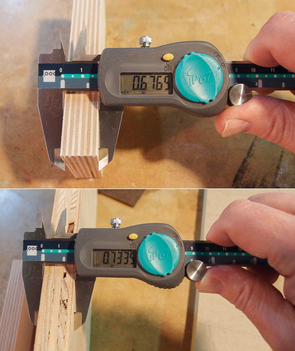
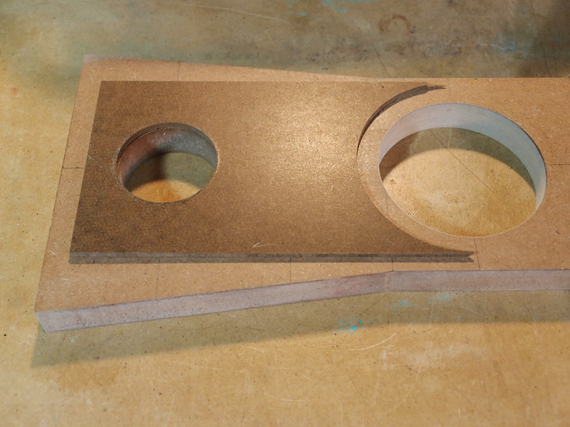
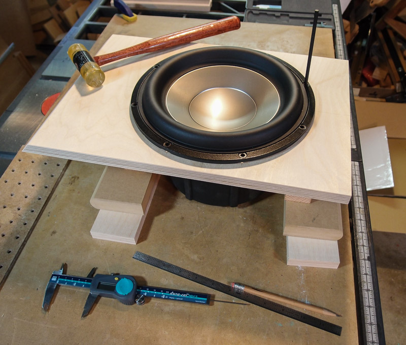
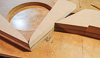
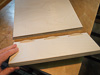
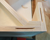
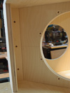
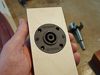
Baffle Material Thickness Issues On the
Orion/Pluto/LX521 owner's forum I posted a couple of pictures of two
kinds of plywood being measured with calipers. I'm not concerned about
increases in strength that come with thickness
My concern is having enough cavity depth to hold the
tweeter. Thin plywood, no matter how well it is made, will not allow the
tweeter to seat. My sample of Baltic birch plywood is only 0.67 or 0.68
inch thick. The hardwood plate attached to the front and to the back of
the baffle is 0.13" thick. Added together, you have a cavity for the
tweeter body that is 0.80 inch deep.
However the tweeter is 0.85 inch deep. It won't fit.
The feature on the back of the tweeter interferes with the rear tweeter
plate (Part C) when it is mounted. (Note that it's not shown in the
illustration to the left.)
One could use a Forstner bit and drill about halfway
through the thin hardboard piece on the rear to provide a space for the
tweeter protrusion. You'd have to do the front plate too because there
are two tweeters. While this is possible, it slows down construction.
If baffle material that is a minimum of 0.72 inch is
used (typical for some USA-specification "3/4 inch" plywood), then the
tweeter hole/cavity inside will be just deep enough to contain the
tweeter. I'd still be worried about buzzes and rattles if the tweeter
fits with zero clearance. If I were using 0.72 plywood, I'd put a piece
of very thin LD polyethylene foam in the cavity first to absorb any
contact. |
| |

 |
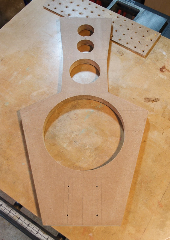
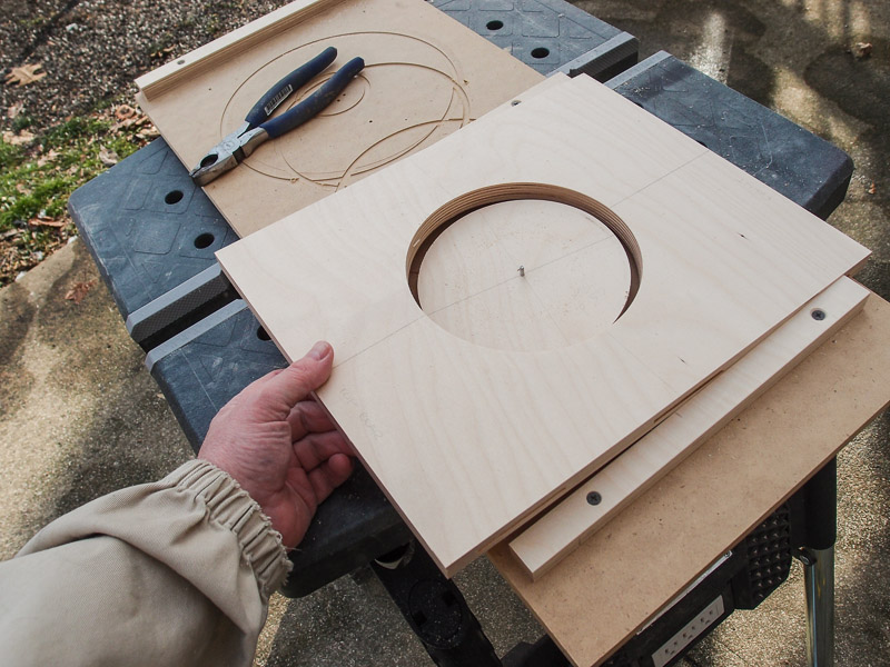
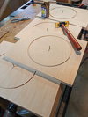
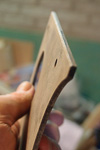
Perfecting the Pattern
Edges Because the baffle pattern was
first cut on a band saw, the edges were not as smooth and straight as you
get from a table saw. However a table saw can't cut the angles needed
for the baffle. The edges were left a little proud of the pencil layout
lines because I knew that I had to trim to the final shape somehow.
To trim the edges right to the pencil mark and to make
them very smooth, I cut some MDF scraps into various wedge shapes for
use. I used double-stick tape to adhere them to the baffle pattern
exactly at the pencil lines.
I took the stack of parts to the router table to do a
light trim pass to match the straight edges of the scraps. There wasn't
much left to remove because the band saw cut was very close to the
layout lines. I estimate
that I had to remove only 1/32" of material in the trim operation.
I cut the left edge and the right edge is two separate
passes. I simply reused the scraps from the left side on the right side
for the second pass. I merely flipped them over and used fresh
double-stick tape.
Easy work. Faster than sandpaper.
I used spot putty on only one edge where the band saw went
very slightly into the line. When the putty dried, I sanded it flush.
Then I gave the MDF pattern a coat
of shellac to "case harden" it for its eventual pattern duty.
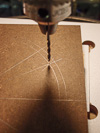
In the last photo, you will spot the 1/8" hole drilled
between the two tweeter bores. It will hold one of the 1/8" metal dowel
pins used to hold the pattern and the work piece in registration. I also
drilled 1/8" holes to mark the centers of the mounting screw holes, and
a second dowel pin will be inserted through one of them for registration. The
two 1/8" steel dowel pins will hold the pattern securely to the stock for
flush trimming around the edges.
The holes are placed strategically in
places that are either hidden later (i.e., under the tweeter
sub-baffle), or are used/enlarged later (one of the mounting screw
holes). I plan to use 1/4"x20 threaded
fasteners through the baffles into the brackets to assemble them. |
| |
 |
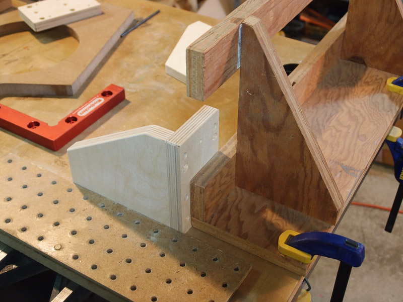
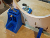
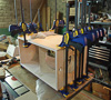
Back to Brackets
I drilled through holes in the base of the bracket
assembly for #6 x 2" deck screws to hold the base and the upper assembly
together. The base is 1-1/4" MDF from stair tread purchased from Lowe's.
I needed to drill perpendicular pilot holes to receive the
screws in the legs of the upper bracket assembly, but the shape of the
top part made that difficult. It wouldn't stand square by itself. I
solved the problem by using one bracket to support the other upside down
bracket. Then I drilled the 3/32" pilot holes square to the
material.
In the router table, I routed a 45 degree chamfer
around the base of the bracket assembly for appearance. Because most of
the base is behind and fairly far from most of the drivers, I presumed
that there wouldn't
be any significant sonic change.
I also made the base for the bracket a slight
trapezoid shape to echo the angular baffle appearance. Angular is in!
|
| |
 |
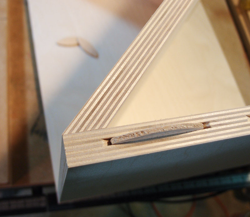
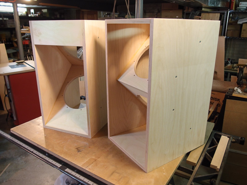
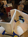
Woofer Box Joinery
I am deviating from the plans slightly in an attempt
to improve upon the joinery of wooden parts for the woofer box. The
items shown in red (Parts A, D, & E in the top picture, and Part C in
the bottom picture) have been slightly changed to meet these goals. This
will allow me to use biscuits to join the baffle to the box in some
areas, and I will move a butt joint to the top surface for visual reasons.
I also plan to miter the angled woofer baffle where it
meets the front of the box.
I completely redrew the plans because I'll use Baltic
birch plywood which measures 0.68" thick. This is somewhat thinner than
the nominal 3/4" material used in SL's plans. To get a tight fit
everywhere, I had to determine new sizes of the parts for the cabinet.
Redrawing to scale allowed me to do this.
For non-owners of plans, I'm sorry I can't present
more detail or show an overall picture here. If I did so, I might be
inadvertently releasing intellectual property. For Linkwitz plan owners,
these pictures combined with your existing plans on page 11 should be
enough to understand my approach. |
| |
 |
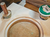
Baffle Material [December 15,
2012] While I was shopping at the local
farmer's market, I saw a vendor selling wooden cutting boards there. It is someone
with whom I have worked on some projects at the university, and his woodworking looked
solid. I asked about getting some cherry boards glued up into a panel to serve as
baffle material. His similar sized kitchen cutting boards were $45 each, and he
said that it would be the same for an all-cherry panel. He also stated
that he could plane the thickness close to what SL has specified in the
plans.
I sent him an email about getting the work done, and
supplied this sketch (sorry about the lack of supplied dimensions -
intellectual property, you know). Cherry should look nice, and I have
lots of cherry boards in the garage for other parts of the build
(bridge) if I
choose to go that direction. |
| |


 |
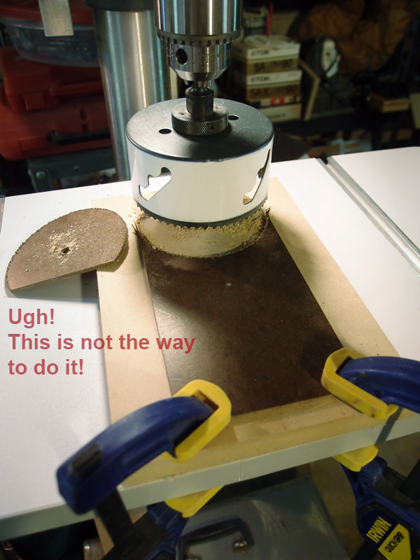
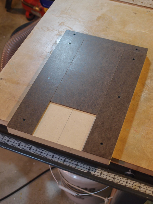
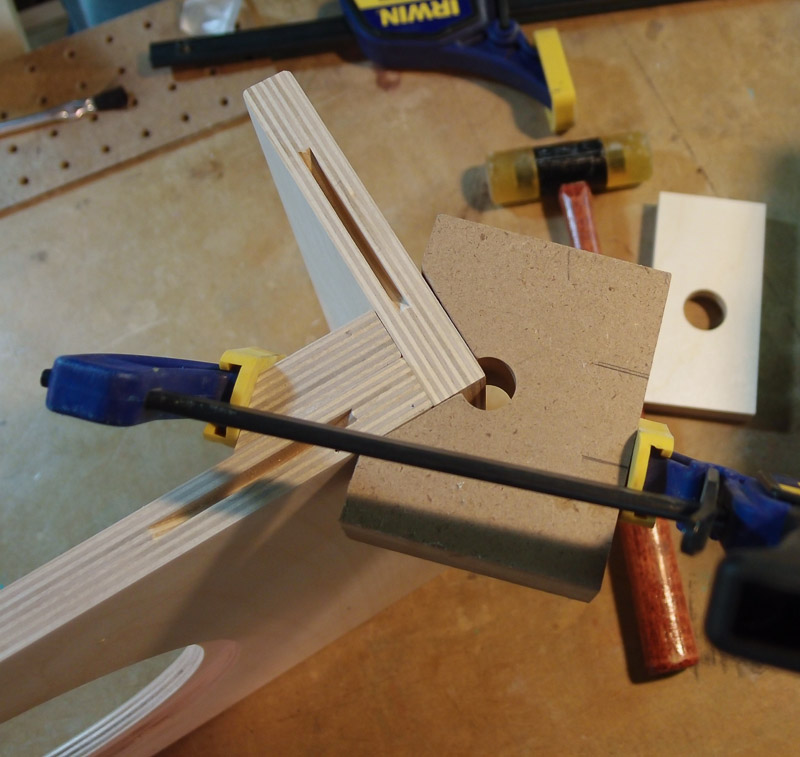
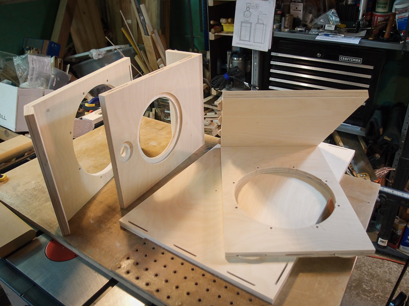
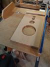
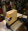
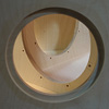
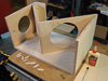
Tweeter sub-baffle fabrication
[December 17, 2012]
I attempted to make do with a hole saw to cut the radius
at the bottom of the tweeter sub-baffle. However hole saws are terribly
inaccurate. This hole saw, almost new, probably has a whopping 1/16" runout. In
addition, the center hole wants to wander, the saw chatters when it
doesn't like the feed rate. It was a miserable experience. The cut edges
were chewed-up and not clean. I decided against doing any more work on
this project with a hole saw. I discarded the parts affected by the hole
saw, and began with a new approach.
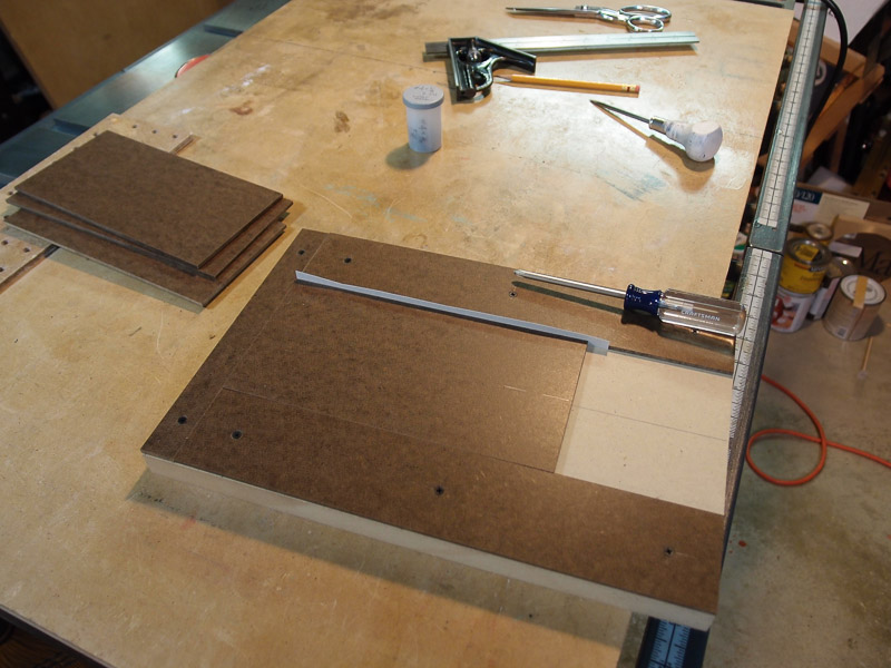
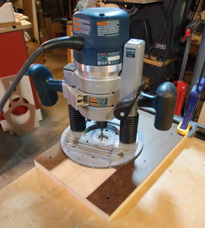
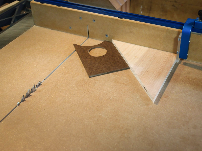
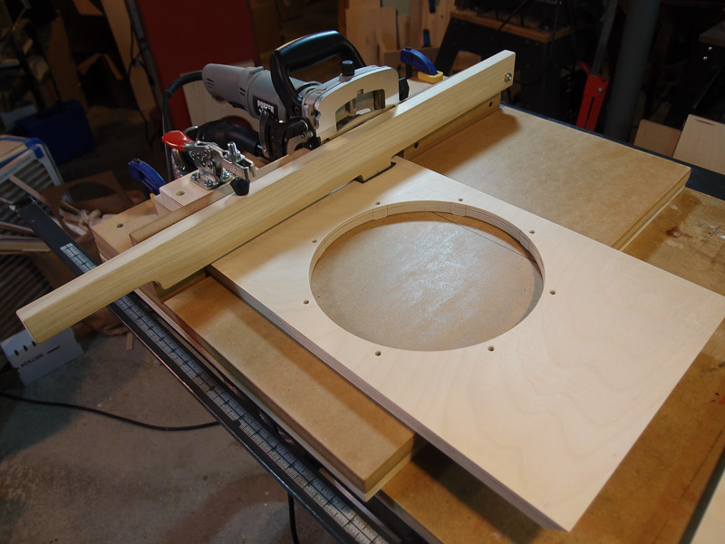
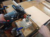
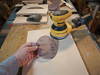
A router, a 1/4" spiral downcut bit, and a hole
cutting jig (a
Jasper jig, in my case) was a better way to go. However,
the tweeter sub-baffle is small and hard to hold. I decided to make a
jig to hold the work. With a little thought, the jig performed a couple
of other duties too, as you'll see.
The jig is made from a scrap piece of 3/4" MDF, and
pieces of Masonite the same thickness as the tweeter sub-baffle. The
work piece has to sit flush on top of the jig so that the router base
passes over it smoothly. To allow a little clearance between work and
the jig sides, I used a piece of heavy paper as a shim. This provided
just a little clearance so that I could remove the work after it had
been routed. It also accommodated the slight variations in the width of
each sub-baffle blank.
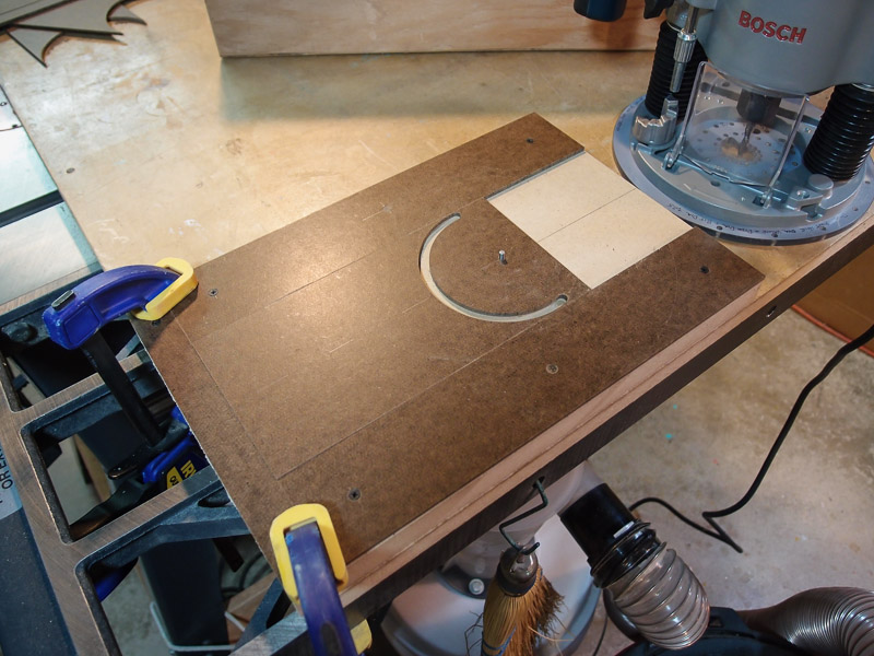
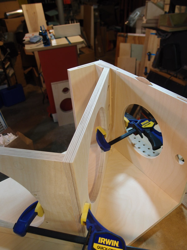
I also carefully marked and drilled three 1/8" holes
in the jig that locate the center of the two tweeter locations (the low
tweeter in front, the high tweeter in back of the baffle and the center
of the arc to be routed on the bottom. The two tweeter center holes are
used to guide a transfer punch for marking the hole center, and the
punch also helped remove the work from the jig. I used double stick tape
to keep the work in position, and it is then difficult to remove from
the jig. Using a transfer punch, a light tap through the jig onto the
back of the sub-baffle loosened it, and simultaneously marked the
center of the tweeter hole. Using the punched mark for alignment, I
bored the tweeter holes afterward using one of the Forstner bits shown
earlier in this build log.
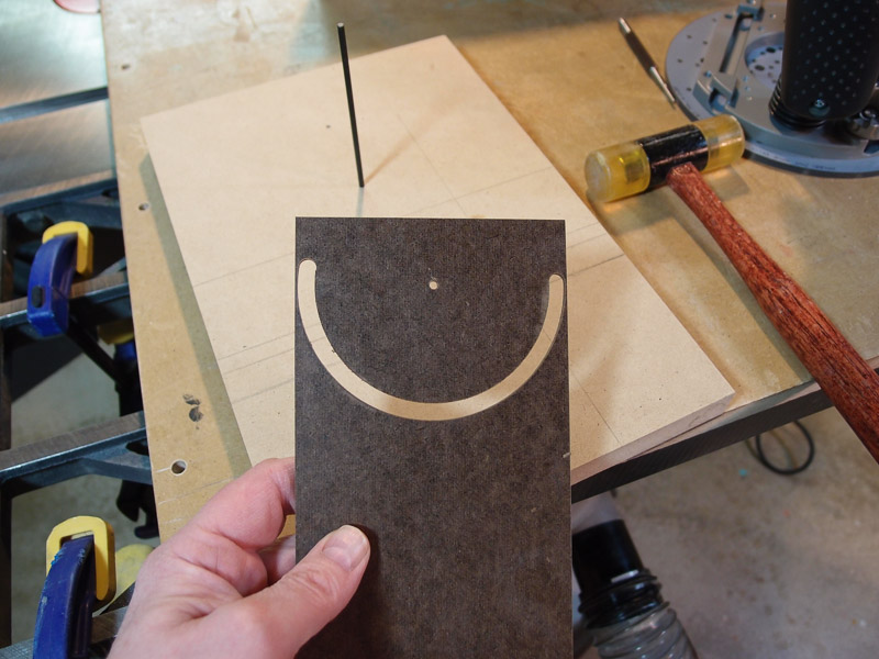
The 1/8" hole located at the center of the arc did two
things - it let me flip the jig over and drill the sub-baffle blank from
the rear for perfect alignment. It then held the pin in location for the
router jig.
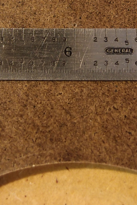
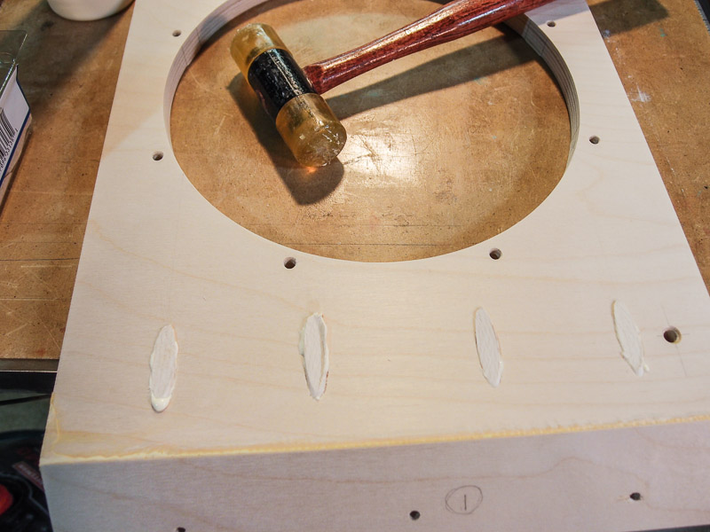
The jig didn't take long to put together, and it did a
satisfyingly accurate job with all aspects of fabricating the tweeter
sub-baffle. The punch marks left by the transfer punch were extremely
accurate. In the second-to-the-last photo in this group, you can see how
the ruler line (the 6" graduation) is exactly at the punch mark when the
left and right edges were on their respective marks.
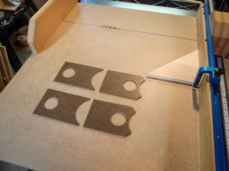
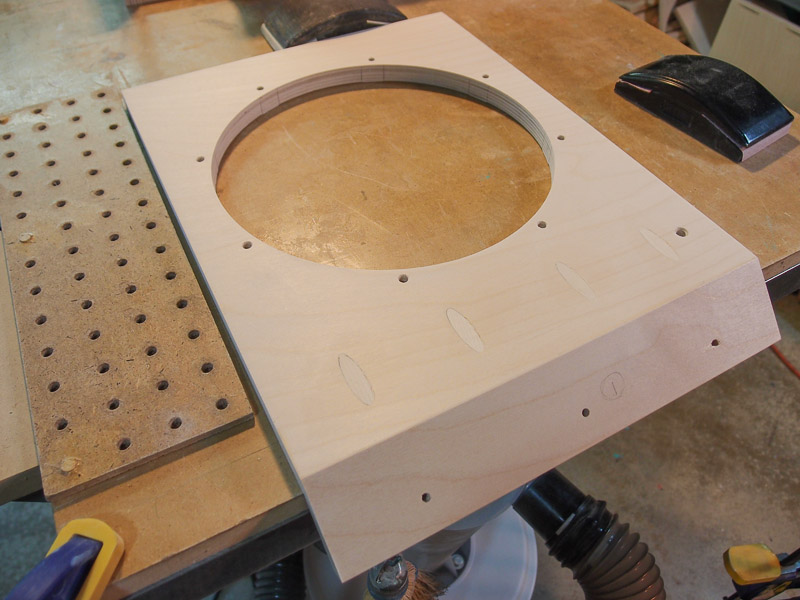
I used my table saw to cut the angled sides of the
front tweeter sub-baffles, and trim the "legs" of the rear tweeter
sub-baffles (per the photos on SL's site, not exactly to plan). All that's left is to mark, drill, and countersink the mounting holes for black #4x3/8" sheet-metal
screws. And paint it, of course.
I'll keep this jig in case I want to change the material
for the tweeter sub-baffle. While it's currently ordinary Masonite, some thin cherry or other attractive
hardwood might look nice. For now the Masonite, painted, will work fine.
I have to keep momentum going on this project. There are
several other commitments looming that will occupy weekends and all
spare time. |
| |
 |
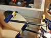
The Woofer Box [December 19 & 20,
2012]
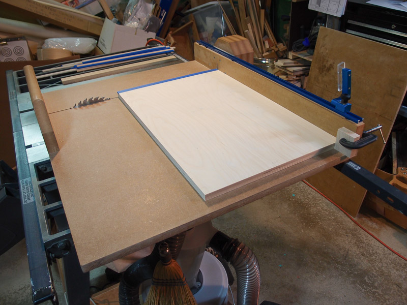
I spent most of today cutting down some 3/4" Baltic birch
plywood for the woofer box. I began outside on a very chilly day cutting
some large sheets to more manageable sizes. I used sawhorses and a
circular saw on a track. After doing that, I took the small pieces to
the table saw for another pass at rough cutting. My goal was to get
clean edges and square corners. After that, it's easy to cut the pieces
to the final size fairly accurately.
I use a crosscut sled for both crosscutting and also
for minor ripping duties. It works well both ways.
When crosscutting, I try to use blue painter's tape on
the cut line to reduce chipping of the plywood. I'm using a 40-tooth
general purpose blade, and it needs a little help when crosscutting
plywood. I dislike splintered edges.
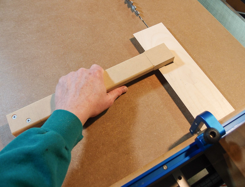
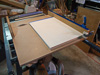
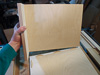
When rough cutting outside on the sawhorses using a
circular saw, I knew that my crosscut sled would handle only 24-1/2"
pieces between the front and back. You can see from the first photo that
I just made it. The width of the piece just fits into the sled.
While I have a
Rockler track and a
flip stop mounted
on my sled, it can't quite reach much beyond 22" without exiting the
track. I resorted to the old-fashioned way of c-clamping a block of wood
to the fence. It worked fine as you can see from the third photo. I have
a detachable table saw stop for crosscutting longer boards, but I
didn't' have to use it today.
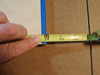
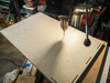
With each speaker build that I attempt, I try to
achieve even more precision than the time before from my tools. I wanted
to rough-cut cut a board to 24", and you can see that I did OK in the photo with
the tape measure.
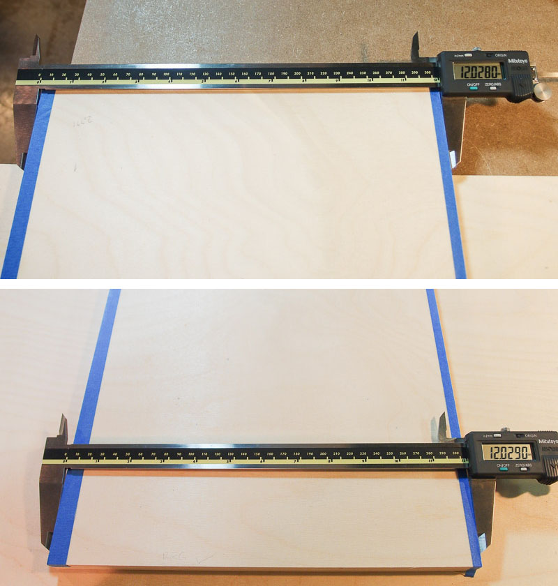
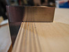
Even better is the parallelism that I get from edge to
edge. Take a look at the measurements made with a caliper at the top and
bottom width of one of the boards. It's parallel to 1/1000". That's
satisfying! [Yeah, I'm bragging a bit! It took a while to get to this
point.] This was a rough-cut to square up all sides with clean edges.
Now if I can keep this precision for all the final cuts!
I now have all pieces F cut to final size, and the top
panels are the appropriate length. There's much more work left on these.
On my Orions, I spent a great deal of time hand
planing the plywood boards smooth and flat before cutting them to final
size. The plywood had a nice, nearly glass-smooth finish after planing.
I'm not doing that here, and I somehow feel like I'm omitting a step
that will ease painting later. We'll see.
Update December 20, 2012
All table saw work is done. I mitered a couple pieces to either improve
appearance, or to improve the joint between parts B and E. I don't have
a crosscut sled for doing miters, but an Incra miter gauge that I had
careful adjusted for squareness did an admirable job. This gauge is used
only on the right side of the blade, and sees little use. After mitering
one end, the pieces were cut to the final dimensions on the other end.
All the cuts look good. If I can't get a square box out
of this, I need a different hobby. |
| |


|
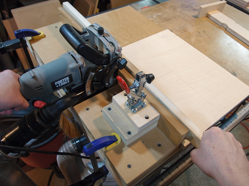
Biscuit Cutting [December 21,
2012] It was cold and it snowed today, so I
didn't go outside to route driver holes. Instead, I took a little time
to cut slots for biscuits, and to check the fit of the newly cut parts.
I like to use a
biscuit cutter because of how it keys
the pieces of a project together. Dry fits are much easier to do because
the tight fit of biscuits in the slots holds them together, and gluing
later on is much easier.
I have thought about the sequence of assembly that
will keep things as square as possible. I'll put the front "skirt" on
the top panel first, gluing them together while both parts are biscuited
together with the side panels. That will register the parts so that they
will fit the side panels exactly later on. I'll remove the side panels
when the glue dries and continue with other parts.
I use a biscuit cutting jig to ease work cutting the
biscuit slots. Over time it has evolved to solve problems that arise -
i.e., warped boards. I have a pivoting hold-down arm that presses the
work flat against the jig surface if the work is warped slightly. I have
been able to apply so much pressure that the MDF base bowed, mis-registering
the slot, so I glued a piece of 1/2" Baltic birch plywood under the work
surface to stiffen it.
To cut face slots in vertically oriented boards, I
have a push stick for safety. It keeps my hands far from the spinning
cutter.
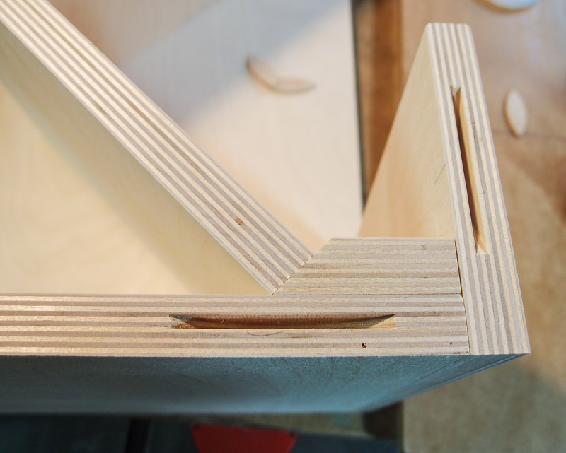
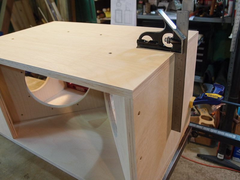
One of the remaining problems I have with the biscuit
cutter is that its carriage has a little up/down slop in it. I'm still
trying to figure out "windage" to give me perfectly flush joints each
time. In one of the pictures, I did it. The metal square is flush along
the joint. In other joints, I applied corrections the wrong way, and
there are slight mismatches between mating parts. Because it was a
bone-headed error, I wrote down the corrections on a reminder sticker
("Press down on handle when cutting face slots") and added that on
the jig. I don't use it enough to remember the steps months later, so I
have to write things down.
However even the larger mismatches are only 0.020"
from flush, so it isn't a big deal. A couple swipes with the hand plane
will level things.
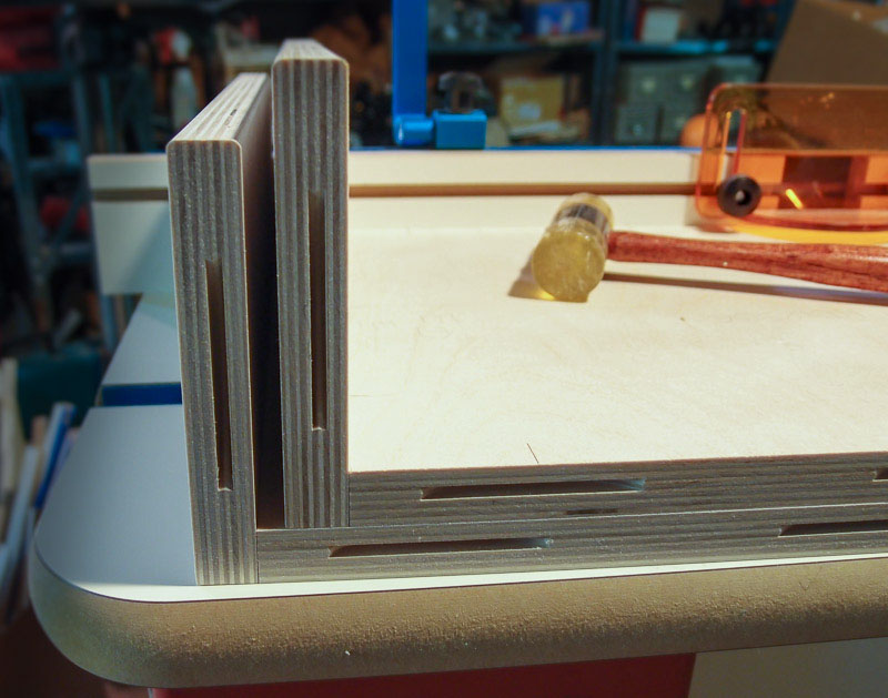
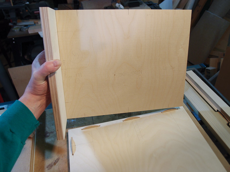
Curious to see if my modifications worked, I dry
fitted even the baffle parts even though they don't have biscuit slots
cut. If I do cut slots in them and the side panels, it will be a tricky
deal, and I will have to remove the cutter from the jig for some cuts. I
have a plan though.
I was very satisfied with how the parts fit together
at this point. The miter cuts on two pieces worked perfectly per the
drawing I made earlier. I deviated slightly from SL's plans here, but I
believe that it will prove to be a better woodworking joint in the end,
and will improve appearance a smidge. |
| |

|
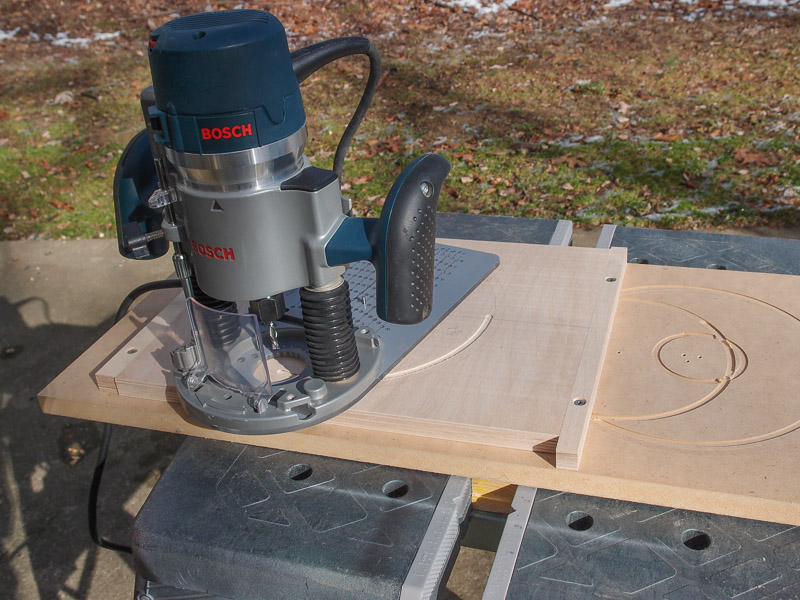
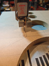
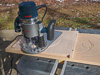
Routing Holes [December 23, 2012]
The weather warmed enough today to go outside for the
messy task of routing driver holes. Sawdust flies everywhere. Outdoors, I
merely use a leaf blower after I'm done to clean up. Indoors, I'd still
be vacuuming crevices for hidden sawdust instead of writing this.
Of course I'm a prisoner to weather. Lately we've had rain, strong
winds, then snow. And cold temperatures that make work outdoors
unpleasant.
I took advantage of today's weather. It began as a chilly 31 F
morning, but by the time I was done, it warmed to 42 F. Snow was
melting.
I used the drill press to drill 1/8" pilot holes for my Jasper Circle
jig. The jig rotates around the pin in the wood, cutting neat circles
and arcs. My first two passes were made with a
Bosch 1/4" downcut spiral
bit. I've found that they leave a cleaner edge to the cut without
splintering. Then I switch to a
Bosch 1/4" upcut spiral bit to finish
the work, cutting through to the other side. The upcut bit cleans out
waste better in deep grooves.
I also noticed something malfunctioning with my router. The
depth-stop fine adjustment was turning rapidly all by itself when the
motor was turned on. I'd estimate that it was completing a revolution in
10 seconds. That's a problem with stepped routing like I was doing today
when each revolution changes the depth by 1/32". To bypass the problem,
I turned the depth stop all the way to its limit so it could no longer
turn by itself. I used the coarse adjuster to get me close. Close is
good enough for this work, but I'll have to remember to look into fixing
that later. [Update - there's a small 3/16" i.d. x 5/16" o.d. o-ring in
the adjuster to provide friction and to seal the threads from debris. It
must be worn, and it's inexpensive to replace.]
Even though I used the downcut bit first to cut clean edges
initially, I still had a couple plywood panels chip at the edges after I
switched to the upcut bit. I tried to sand a small bevel on the
remaining panels with a sanding sponge, and it seemed to help, but not
eliminate, the problem. Thankfully the chipped edges will be hidden by
driver flanges or will be rabbeted to a larger diameter in the case of
my top panels.
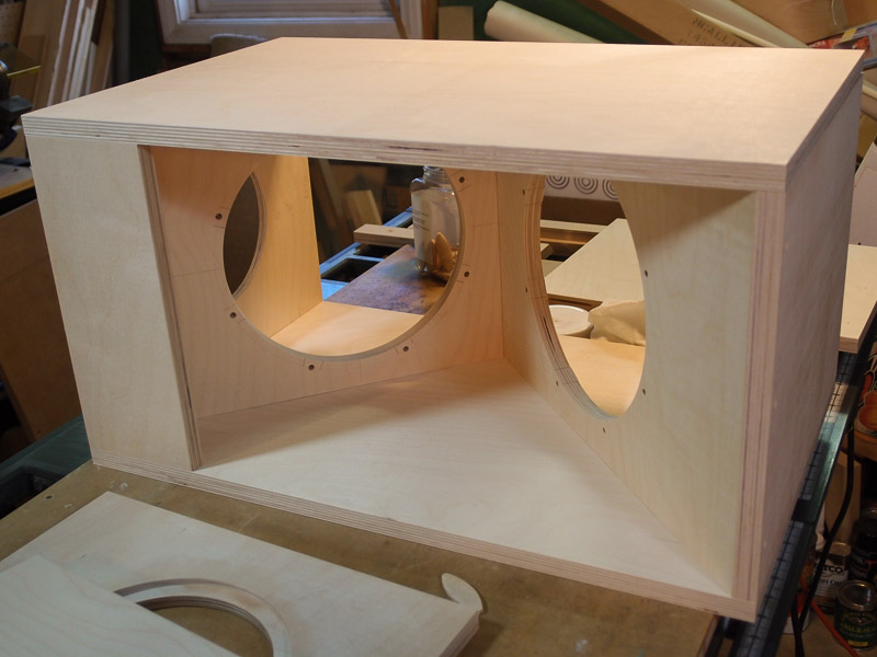
I still need to rough cut some 1/4" hardboard, then route the
circular covers for the tops of the woofer boxes. I cut openings in the
top of my boxes to allow for access when mounting the heavy woofers. The
openings will allow easy use of tools. It will be covered up with the
circular covers after drivers are installed. If you are thinking of
manhole covers found in streets, you wouldn't be far off. Same concept.
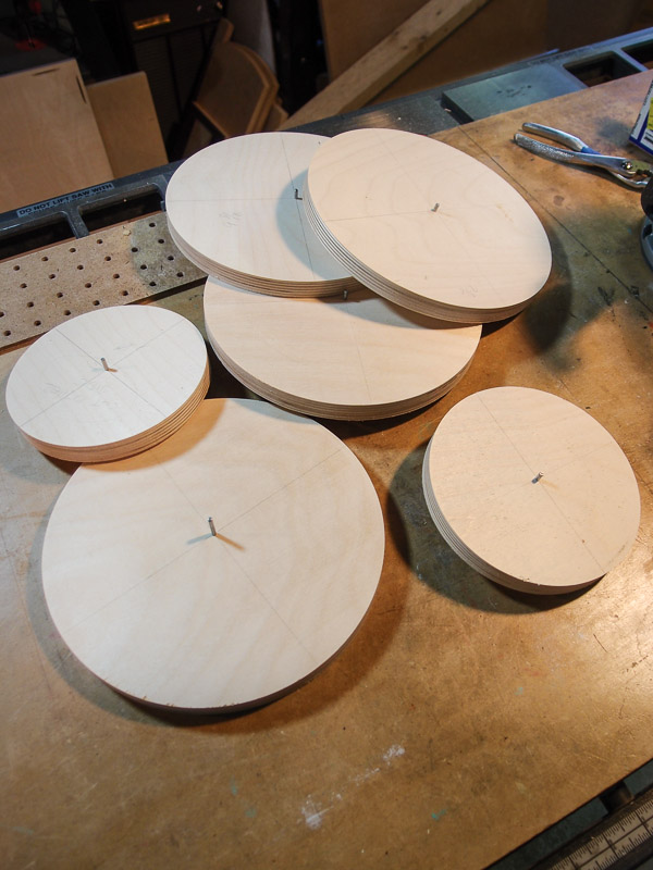
Now, If anyone has a really clever use for the 3/4" thick disks left
over from speaker building, just let me know. I'm starting to collect
way too many.
|
| |
 |
Marking and Drilling Woofer Mount Holes
[December 25, 2012] I spent a little time in the workshop today
marking and drilling screw holes for the woofers. The shop was very cold
today. I'll have to start wearing a coat in there when I work.
To mark the screw locations, I place a woofer into the routed opening
and center it using some marks made with a square and some little
punches made with the tip of my calipers. The original pencil centerline
is still visible for use. I measure the center to center distance of the
actual holes in the woofers, divide by two, and set the calipers to that
distance. I reference from the centerline and make a left and right hand
scratch using the calipers on either side of the centerline. Then I use
the combination square to draw short lines through the caliper
scratches. The steps are repeated on the left side, which is 910 degrees
opposite the original marks.
These lines are visible through the woofer mounting holes when it is
positioned correctly. The woofer sits in an opening that is about 1/16"
(for me, at least) larger than the driver itself, so these lines aid in
centering the woofer in that opening. It isn't perfect, but it gets me
close.
Once the woofer is positioned as desired, I use
transfer punches through the woofer mounting holes to make a small
center mark.
Afterwards, drilling the holes is a piece of cake. I drilled the
holes large enough (7/32") to easily accept #10-24 screws. I'll use
locknuts and washers on the back side. |
| |

 |
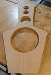
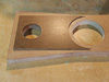
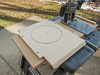
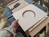
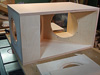
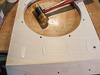
Treating Edges [December 26, 2012] I managed
to cut the recess for my "manhole cover" in the top of the woofer box.
It will allow access to the top woofer when it comes time to mount the
driver and solder wires. Note that this is my modification, and is not
part of SL's plans. I will fabricate round pieces of 1/4" hardboard to
fit into the recesses. They will be installed with weather-strip gasket
material to make a tight, rattle-free joint.
I cut the recess on my router table using a
1/2" rabbeting bit. I knew that this plywood was susceptible to
splintering from my earlier routing work, so I applied some shellac
around the area to be cut. My thinking was that the shellac would sink
into the top wood fibers and serve as a glue, binding them together. It
was an experiment to reduce the tearout.
It didn't work. Even with a very light first cutting pass, I had
fairly significant splintering of the wood along the cut edge.
Thankfully the woofer box will be painted, and Famowood-brand
wood filler is an option to hide the chipping. With a couple of
applications so far, it looks good.
Hindsight thought - the Bosch 1/4" down-cut spiral bit worked best
with this plywood to prevent tearout. I should have made a light scoring
pass with it before cutting the through hole in the part. [Hindsight
alert #2. What the heck - maybe cut everything with the
spiral down-cut bit! I wonder what sort of new problems that would bring
about?]
I'd like to find a way to put a 1/8" radius along the cut edge, but
no router bit I own will fit into the shallow recess to make the cut.
Even the small-pilot Dremel bit that I ground down hits bottom in the recess
before the cutting edges make contact. I'll probably just use some
sandpaper to ease the edges and be satisfied. In the end, this part is
mostly hidden beneath the bridge anyway.
I revisited the tweeter sub-baffles with a
small block
plane to chamfer the edges along the sides and tops. This went very
fast, and took only 10 swipes down each edge. It's looking more finished
now. Primer and paint will come later - probably in spring when the
weather improves. |
| |

 |
A Day of Drilling [December 27, 2012] I needed
a way to clamp the angled baffle to the bottom of the woofer box for
when I glue them together. There's nothing simpler than using screws to
clamp a joint tightly while glue dries.
I didn't want the screws to show from the listening position, so I
planned to insert them from the bottom of the box into the miter. To
estimate position and depth, I stood the pieces on edge, and just placed
different screws into position - by eye. I settled on #8x1"
self-drilling screws from McFeeley's as a good length if I counterbored
the screw hole about 0.150" below flush. They were positioned about 0.7"
from the box's front edge.
Because of the need to counterbore and to countersink the land for
the screw head, I used a countersinking tool that does it all
simultaneously in one drilling operation. My kit is cheap, and the
cutting edges are fairly dull, but the #8 bit did an OK job considering
the tool quality. Once decisions were made considering screw size,
placement, and depth, the drilling went very fast.
I also placed three mounting holes in the piece at the top inside of
the box. The screw holes here won't show either. They will assure a good
clamping pressure when the time comes.
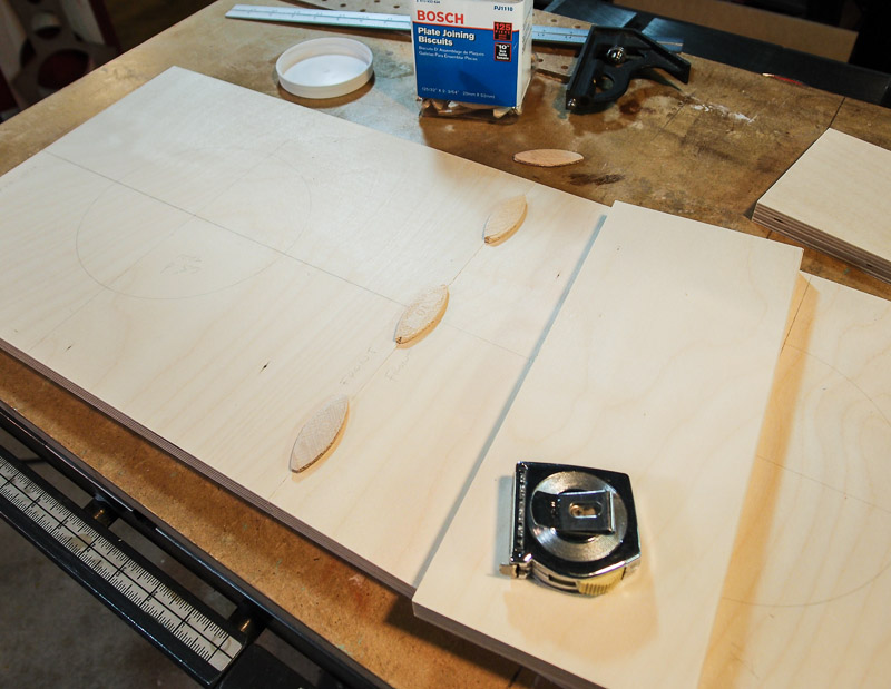
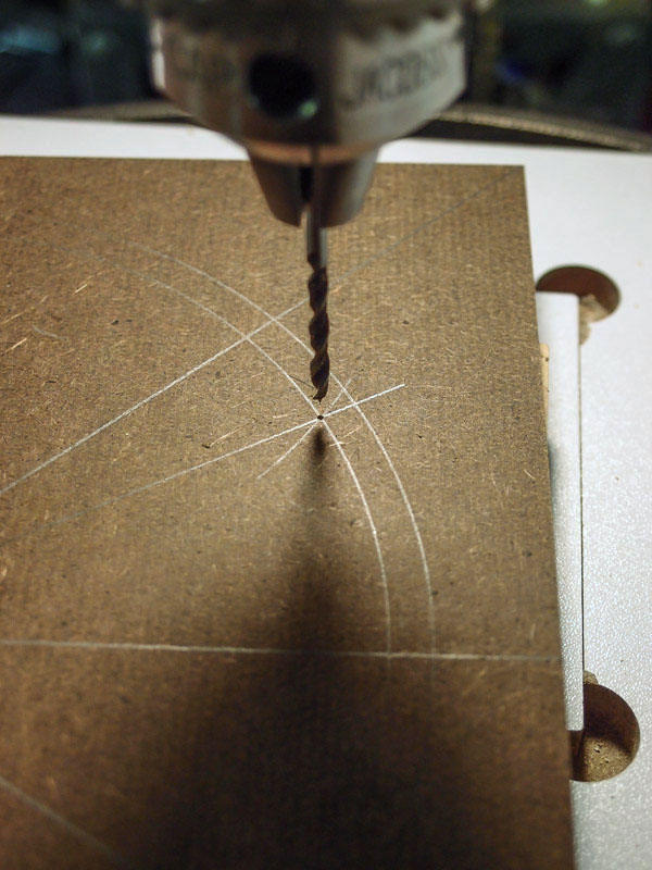
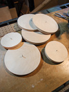
I needed to fabricate the "manhole covers" that cover the access holes
in the top of the woofer boxes. I will make these 7.5" round parts from
1/4" hardboard. After rough cutting some square blanks, I drew the cut
outline. Before I cut away the center, I also drew the bolt circle for the
mounting screws. I plan on using 6 screws in each cover to hold it in
position.
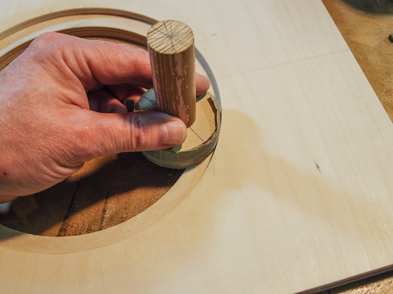
From mathematics, when you adjust a compass for drawing the desired
bolt circle, the compass radius is exactly correct for marking
the spacing between the 6 holes on the bolt circle. I drew arcs that
intersected the bolt circle to mark locations for the screw holes. I
plan on using small #4 x 1/2" flathead screws to mount the covers to the
top of the boxes. I also contacted Madisound by phone today to add
items to my order before it ships. I added 8mm female quick disconnects
for spade terminals (part
number QC8MM) to fit the large woofer terminals. The
quick disconnects that I added to the order don't cost much money, but
by including them in the driver order, shipping costs are essentially
free. |
| |
 |
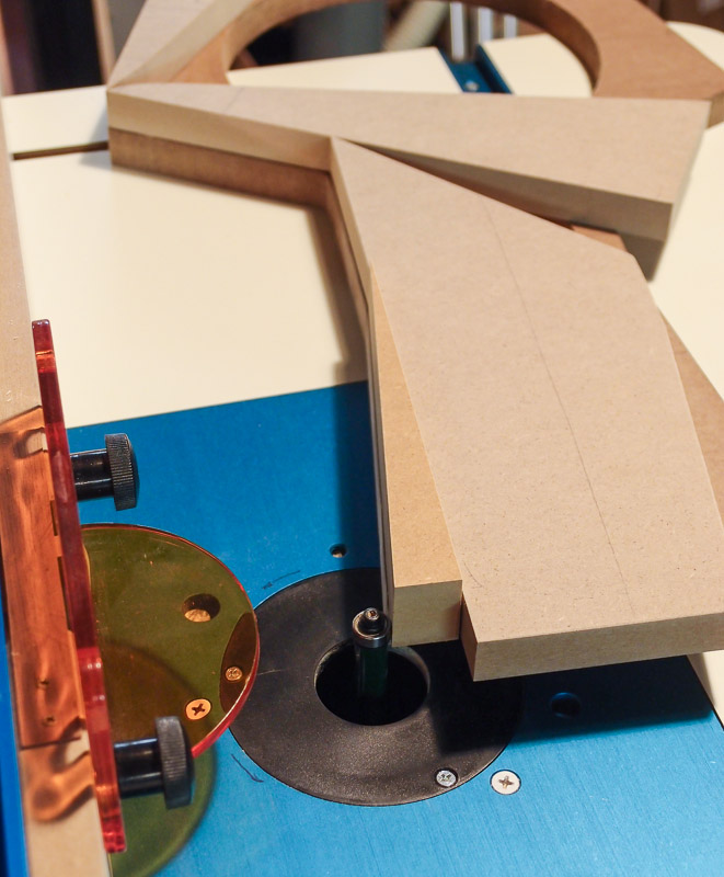
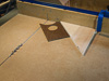
More Woofer Box Work [December 28, 2012] I
didn't have as much time today as I'd like, but I got a couple of things
completed for the project. First, I routed the "manhole covers" from
1/4" hardboard using a downcut spiral bit - outdoors at 31 degrees F.
Brrr! I made the OD 7-7/16 inch to allow a 1/32" clearance all around
(1/16" total difference in diameters). The rabbeted recess for the
covers was within a couple thousandths of an inch of the 7.500" target,
and I knew that I had to allow a little extra room for paint.
Back inside from routing, they looked good in place. There's a small
1/8" pivot hole drilled through the center of the piece for the router
jig, but I will probably not even attempt to fill it with Bondo or other
filler. It will be too small to make any difference at the woofer
crossover point of 120Hz, and it's hidden under the bridge.
I also cut biscuit slots to join the two angled baffle pieces inside
the box. I might choose to not screw them together at the joint,
but to just clamp in position for gluing.
After all that was done, I did another dry fit of the parts with
biscuits inserted to hold it all together. The fit was very good. I'm
still pondering methods of placing biscuits accurately enough along the
sides of the baffles to avoid running screws through the side walls of
the enclosure. Screws are simple, and will be mostly hidden by the
bridge of the top units, but there's something about the challenge that
appeals to me. We'll see if cold logic (use screws!) wins out, or if I
attempt new techniques to get good registration with biscuits.
At any rate, the fit was good and I'm pleased with progress so far. I
am looking also for a way to fasten the top angled baffle to the miter
on the spacer to hold it in place while glue dries. Nothing appears
easy, but drilling pocket screws at a 45 degree angle is one
possibility. The drill press table tilts, and I'd have to clamp securely
to do this. It seems like a lot of work though.
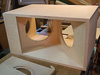
One last photo in this group was made looking through the "manhole
cover" port on the top panel. Because my shop is illuminated by
different compact fluorescent bulbs mounted in round clip-on fixtures,
the color temperature for photography varies among them. The differently
angled pieces were illuminated by the different color temperature bulbs, and
I found the effect fascinating. Consider it speaker art. Today, I
ordered some items from
Parts Express
for the project. I plan to inset
round Speakons into the tops of the woofer boxes, at the rear. That
will make it easy to connect and disconnect the mid/tweeter part from
the woofer box for moving. I expect that I will need to adjust position
many times once they are in my listening room to find the best sound.
I've never had dipoles before, and I'm sure that they will react
differently to my room's acoustics. While I could surface-mount the 2"
diameter Speakons, they will look better recessed into the top surface
of the woofer boxes. I'll use a
2-1/8"
diameter Forstner bit to do that. Forstner bits are available in a
Woodcraft store that's about 45 minutes away by car, but the we have
about 5" of snow on the ground and it is still coming down. No driving
today for non-essential items. |
| |
 |
Not Much to Report [December 29, 2012] I
sanded the parts for the woofer boxes today. It's boring work, but some
sanding needs to be done before assembly. After assembly, access becomes
limited for interior parts.
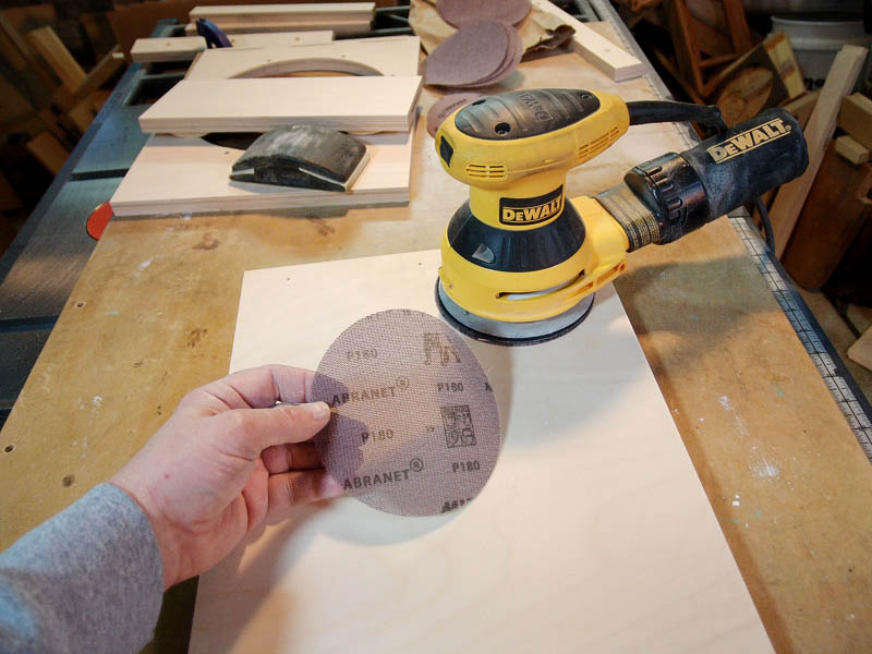
I did manage to try some
Mirka Abranet sanding pads on this project.
I've heard good things about them, so I bought a small assortment to
try. I began with 120 grit, and followed that with 180 grit. They worked
well.
Dust, however, settled on everything in the shop. Even with the dust
collection bag built into the sander, fine dust managed to get
everywhere. While it's possible to attach a vacuum to the sander, I
couldn't run my Shop Vac for a couple of hours without damage, or
blowing the circuit breaker on the power strip. I suppose that I should
refrain from power sanding indoors, but the weather outside is
miserable.
I have some cleaning to do. |
| |


 |
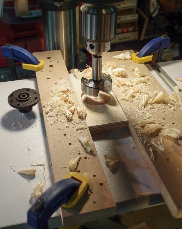
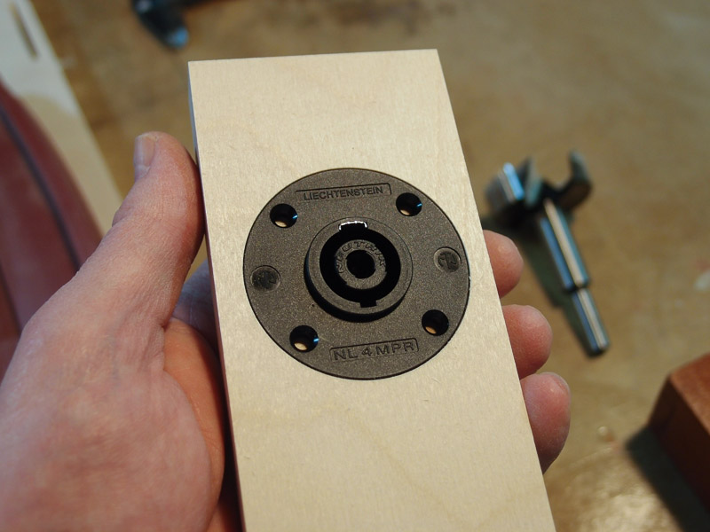
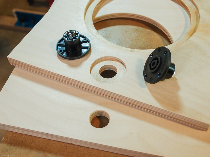
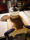
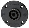
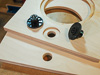
Holes for Speakons and Pocket Holes [December 31, 2012] The
Speakon quick-connect parts were ordered from Parts Express on Friday.
They arrived via FedEx this morning around 10 am. That's fast service.
I drove to Woodcraft in Parkersburg yesterday to pick up two Forstner
bits - 2" and 2-1/8" diameters. I though that maybe I'd try the
smaller 2" even though the Speakon is 2" also. Having both the recess
and the part 2" in diameter provides no clearance in the
recess for paint, etc. However stated specifications are sometimes off a little,
so I thought that I'd try it anyway.
It worked. I'll have a little paint buildup in the recess,
but I can always file the outside of the Speakon flange a bit to make it
smaller. The tight clearance looks very tidy, and I was afraid
that going to the larger 2-1/8" recess would look sloppy by
comparison.
I began by trying the
2" WoodRiver bit (their house brand, usually Asian in origin) on a
piece of scrap plywood. Even though the WoodRiver-brand Forstner bit was
inexpensive ($12.59) compared to a higher-quality Famag ($46.19),
it did a great job. Both the 2" and the 2-1/8" WoodRiver bits were in
stock, too, which wasn't the case with the Famag brand. I did use a
fine-grit diamond file to touch-up the cutting edge of the 2" bit before
I used it. It had a burr on the leading edge that was easy enough to
remove.
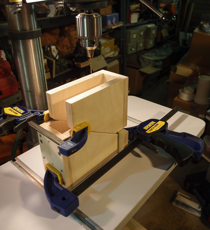
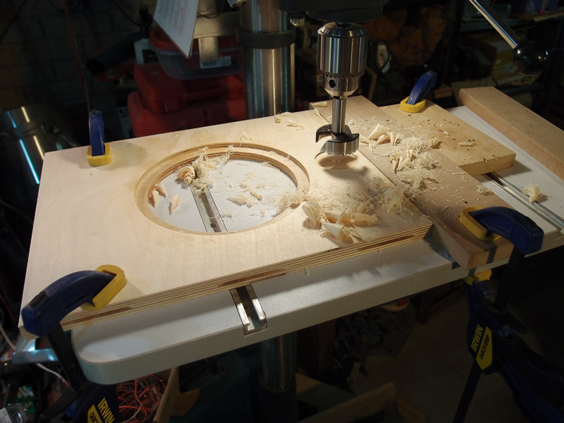
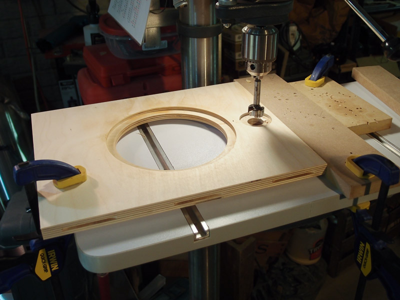
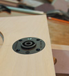
Once the test with scrap wood worked out OK, I went on to the real
baffles. I set up a fence of sorts on the drill press so that the baffle
wouldn't move around much. It also aided finding the center when it came
time to cut the 1" through-hole with another Forstner.
Once the holes were cut, I rounded the underside through-hole edge on
the router table. The 1/8" chamfer bit was already in place in the
router table, and it took about 10 seconds per panel to do. Now I won't
cut myself on sharp, splintery edges when it comes time to wire the
Speakon.
This work should really pay off when it comes time to move the
speakers to find the best sound. The Speakon quick-connect system is a
proven design. A few more preparatory steps (drilling wire holes,
etc.) for the woofer box panels, and I should be able to glue-up soon.
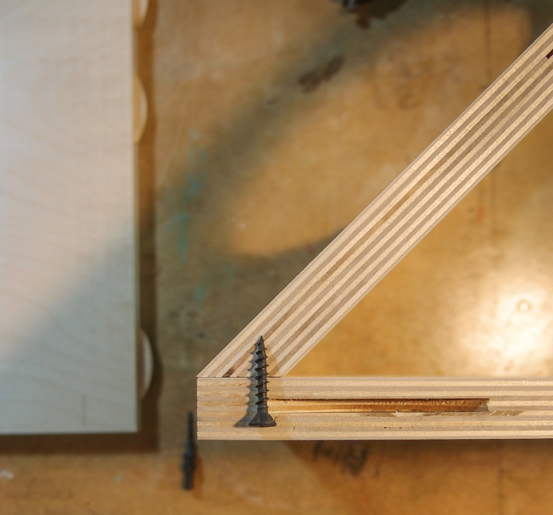
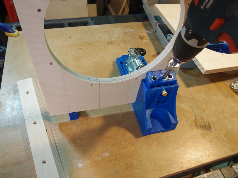
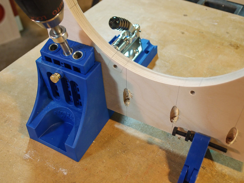
I also cut some pocket holes for the upper baffle. I need a way to clamp
it for gluing, and pocket holes with screws made sense here. I used my
Kreg pocket hole jig to cut the holes on an angle. The 1" long screws
will exit the baffle at its end and enter Part E. I'll drive the screws
after glue is applied and other box parts are positioned correctly to
ensure a good fit and squareness.
For now, I just placed the parts on
end to get a sense of the arrangement. If I can, I'll use the Kreg plugs
to fill the pocket holes. Even though they are well under the top panel
of the box, I don't want to see them if it's possible - even when I
crouch down behind the speaker. I didn't have enough time to begin
gluing, but I did start planning the wiring run, and where to
put through-holes in the baffle. I am planning to place the larger
8-pole Speakons left-of-center on one speaker, and right-of-center on
the other. It will shorten the speaker cable run a few inches, and I
believe the wire routing makes more sense visually. A big wire in the
center splitting off left and right didn't seem appealing. I also plan
to use Wood Artistry's Speakon brackets instead of fabricating them from
wood. I'm borrowing them from my Orion build because it will be easy,
and because of appearance. |
| |
 |
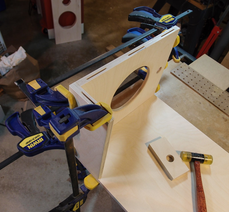
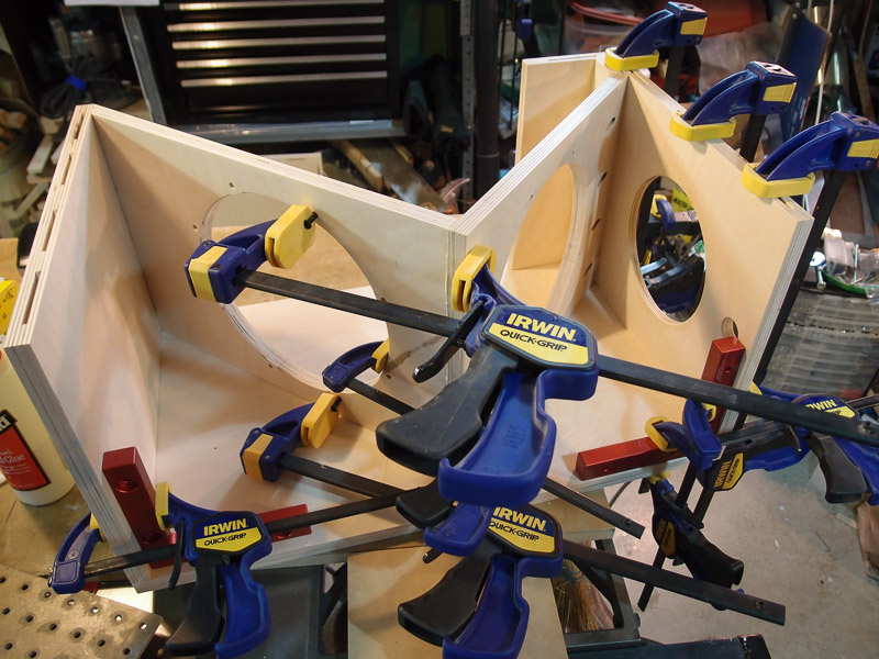
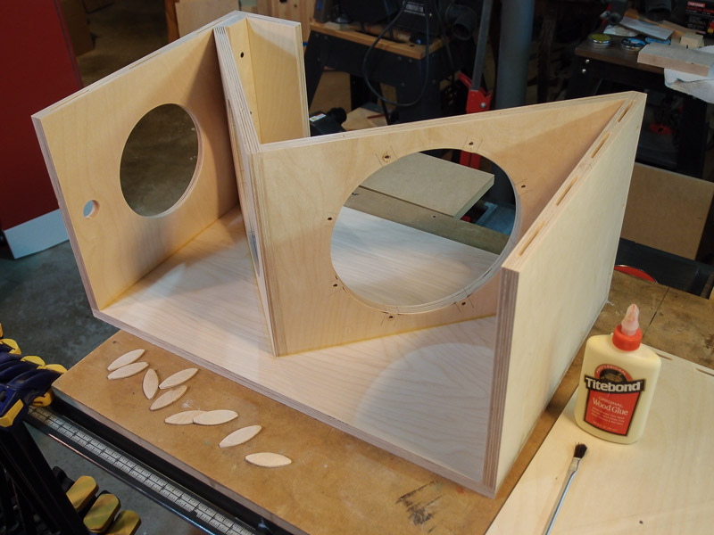
Gluing Begins [January 1, 2013 - New Year's Day]
I had all day to work on the speaker today. No interruptions, nothing.
I began to glue together some sub-assemblies. In the first photo, I
glued the top panel to the short front panel. I did not glue them to the
side panel. Because I used biscuits, I could use the side panel as a jig
for gluing. To prevent the two pieces being glued from sticking to the
side panel, I put some wax paper between the top/front pieces and the
side panel. After about an hour, I pulled the now-glued top and front
panels from the side panel for further work.
I needed to run the clamping screws through Part E into the top panel
accurately, but was having a little difficulty with the piece moving
while driving screws. It has a miter which makes clamping more
difficult. To solve that problem, I used a corner clamping block
made for another project to apply firm pressure to the part, and drove
the screws home.
Now it was time to glue the upper baffle to Part E at the miter. I
positioned the parts using one side panel as a jig, and used the pocket
screw holes that I drilled yesterday for clamping screws. I allowed the
glue to dry several hours for this sub-assembly because of the small,
unsupported glue area. I wanted to be sure of a solid joint.
After a safe period of time passed, I pulled everything apart again
and plugged the pocket screw holes with Kreg plugs. They were Maple
(close enough) and were glued in place. After the glue dries, I'll use a
hand plane to trim the plugs flush to the surface. Right now, it looks
fairly rough.
One thing that I noticed with all the fitting is that the side panel
material is slightly bowed. I'd have to clamp with a considerable
pressure in the center to ensure good contact with the baffles. If I
were to use biscuits, that would mean clamping with cauls. That's too
much work, so I made the decision to use screws through the side panels.
I spaced the holes for the #6 deck screws 5" from the front edge and 5"
from the back edge where they intersected the baffles. To do that, I
positioned everything in its final assembled position, then traced the
baffle edges onto the side panels with pencil.
It's not ideal to have screw holes in the sides of the boxes, but
they are flat head and countersunk. . I located the screws so that
they'd be covered the bridge of the speaker, and not visible in normal
use. I've milled countersinks for them about 0.020" below flush which
will allow me to use Bondo putty to cover them over, if I wish to
anyway. |
| |


 |
More Progress [January 2, 2013] Yesterday I
filled the pocket holes with wooden plugs. The glue dried by morning, so
I planed then sanded the protruding parts of the plugs flush with the
surface of the baffle. When painted, you won't be able to see the plugs
at all. Also, this is up very high underneath the woofer box, so you'd
have to crouch to see them anyway. It was just something to do while
glue dried elsewhere.
I had forgotten to mark the screw locations for the "manhole cover"
on the top panel, but with only #4 screws, pilot holes were not
necessary. Good thing, the top panel had the short front panel piece
already glued to it making difficult the use of the drill press. With
the little #4 screws, all I had to do was to use some heavy cardboard
(measured 0.023") as a spacer to center the hardboard cover in the
recess, then drive the screws down. Easy.
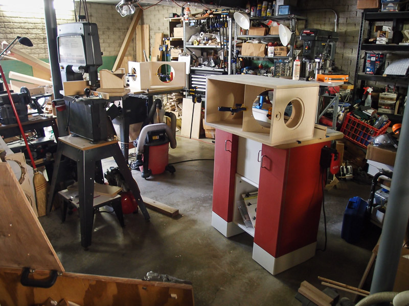
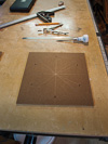
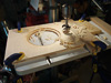
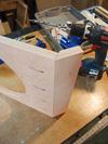
I included a picture of my very small, crowded shop with both of my
"work tables" occupied with work. The "work tables" are a piece of MDF
on my table saw, and the top surface of my router table. Oh, and the
little 12" square top of my cheap band saw. The room is located under my
garage, and has low ceilings too. Access is limited, and it's crowded
because of its use as a storage area too.
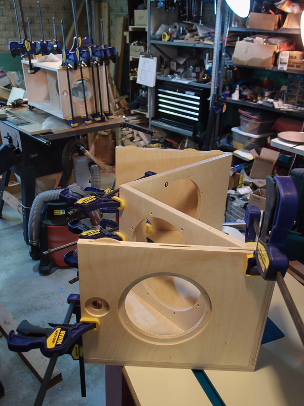
When the glue dries, I pull the subassemblies from the side panels
and move on to other pieces that need work. [Later today - more
gluing] I began gluing up the sub assemblies into the part that fits
between the side panels. I forced parts square to the side panel that is
used as a jig for the assembly and gluing. Note that I left these pocket
screws open - I inadvertently glued the small Part E to the top panel
before I realized that wouild make it very difficult to clean up the
plugs. It's not an issue structurally. Even the appearance isn't
affected unless someone crawls around on their knees looking at the top
part of the woofer box, and even then it's neat. It's one of those
things that bothers me more because I did a step out of plan. To clamp
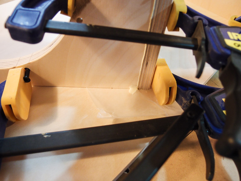
the two baffles together without using screws, I used a 6" clamp through
the woofer hole, and two others pulling on bolts that I had inserted
into the driver mounting holes. It made a handy grip point for applying
good clamping pressure for the glue. There are biscuits in the joint
too, and those were liberally glued before insertion. Note the use of
wax paper to keep the squeezed-out glue from adhering the assembly from
the side panel. I will remove the glued together parts tomorrow for a
little more work (drilling pilot holes into the baffle edges) before the
final step - attaching the side panels.
Working step-wise like this allows me to check the quality of fit as
I go. If everything were glued at once, I wouldn't have time to check
squareness, adjust clamps, whack pieces into proper alignment, etc.
before the glue set up. I don't have enough arms and hands for that sort
of approach. Note that some of the clamps you see in some of the
pictures aren't being used for clamping glued joints. I'm using some of
them to flatten a slight bowing in some of the side panels, and in
others, I clamp assemblies square to each other. By clamping them square
to another part and flattening any slight warping, I simulate the
position in which the pieces will be eventually assembled. |
| |

 |
Gluing Again [January 3, 2013] Gluing takes
time when faced with limited work space and clamps. I've begun gluing
the side panels to the center assembly. I noted with some irony how
square things are before the glue goes on. I know that the gluing
process, being somewhat rushed, always tweaks squareness. I wish there
were a way to assemble the panels and then somehow wick the glue into
the joints. Plastics, yes, wood, no.
I'm glad that I put 4 screws through the side panels to tie it to the
baffles. It would be very difficult to apply pressure on the mid-panel
without using some sort of cauls. I still resorted to using one
makeshift caul because of the bow of the side panel. It was barely
making contact between screws in one location. I placed a piece of
scrap plywood on top of the panel with a few folds of paper towels in
the center to apply local pressure. It's not ideal, but it did take out
some of the bow of the panel and made a little better contact with the
baffle edges. It would have been OK without it, but it helped, I'm sure.
I finished gluing the sub-assemblies together on the other box. This
time I was a little better prepared for the baffle clamping by using
screws, washers and nuts at the clamping point. The last time, it was a
rush to jam the screws through the holes while glue was setting. It
worked, but this looks tidier and it places less stress on the wood
around the baffle holes.
I've employed just about every clamp that I own today, as well as
both flat surfaces on which to work. Naturally, after gluing, I can't do
anything more while it dries.
I'll probably not update this log for a few days until gluing is
done. After all, how many pictures of clamping/gluing do you want to
see? (If you think this is bad, just wait until spring when it comes
time to paint. Prime, sand, spot putty, prime, sand, etc., etc., etc....
Flash update....
Madisound
sent an email stating that the back-ordered drivers have shipped. I'm
officially behind now. |
| |

 |
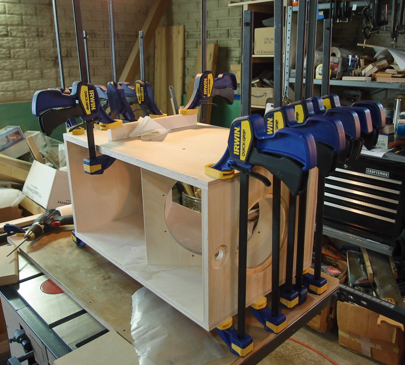
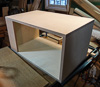
Woofer Box Gluing DONE! [January 6, 2013] The
top picture in this group shows the last box about to have its final
side panel glued on. That was the last gluing task for these boxes. I
finished gluing the woofer boxes together yesterday, and removed the
clamps this morning.
Time to step back and take a look.
They are looking good. Not perfect, but very close. As I expected,
gluing tasks aren't exact, and a little sanding here and there to flush
some joints is still needed.
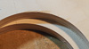
I am very pleased with the 45-degree miter at the lower front edge.
That came together very, very well, and only the slightest touch up was
needed at the front edge to make it perfect. I sanded a very small
radius there to blend the angled piece with the box. There's no gap, no
ridge, just smooth goodness now.
Squareness of the boxes is also very good.
I still have to sand away squeezed-out glue from the joint locations.
When it warms up in spring, I will probably use some sort of grain
filler or heavy, sandable primer to hide most of the appearance of
wood grain from the painted surface. The plywood edges are particularly
visible without a little work with fillers, primer, then paint. I know
that from experience with the Orion woofer box.
My available free time left to work on these is rapidly disappearing.
I have the rest of this week away from work, then I will be very busy
for a while. I will have small bits of time in the evenings, and on the
weekends (those that I don't work), so maybe its time to start on the
electronics. Electronic assembly work is more suitable for small blocks
of time. |
|
|
|
[continued on page two] |
 |
|
|
|