Improving the motion of an Omega DII enlarger head
Most enlargers have a movable enlarging head. The head is raised to produce larger prints, and lowered for smaller sizes. Omega enlargers use flanged plastic bushings that are supposed to roll against the enlarger rails when lifting or lowering the enlarger head. Over time, wear may produce flats in them, preventing a smooth lifting action. They probably didn't roll that well to begin with anyway.
I use an older Omega DII enlarger that doesn't have a hand crank. The head is raised and lowered by hand. I've replace the plastic bushings on my DII enlarger with a combination of flanged roller bearings and bronze bushings (the bronze bushings are covered with PVC flexible tubing) to make the action MUCH smoother. It's now easy to increment the enlarger head height just a little for minor adjustments to image size.
A full report including step-by-step instructions and a parts list can be found in the March/April 2005 issue of Photo Techniques magazine (the issue is now unavailable except for library archives). I have placed a PDF file scanned from the original magazine pages here.
The magazine story also described some limitations and workarounds for the newer hand-cranked D2 models. The rack and pinion lift mechanism interferes somewhat with a full bearing replacement, but some improvement is still possible. (I'll add this information to this page as I find the time.)
The story follows...
New Life for Old Omega Enlargers
(Originally published in the March/April 2005
issue of Photo Techniques
magazine)
By Larry Hamel-Lambert and William Schneider
One of the most common darkroom enlargers is the venerable Omega DII-series, and with digital photography displacing many home darkrooms, these enlargers can be found at rock-bottom prices.
This is a boon for the traditional darkroom worker who wants one, especially those working in medium and large format where comparable digital quality comes at a prohibitive price. In addition, the look and feel of a traditional b/w silver print is still unique -- enough so that silver prints still command attention and higher prices in a market saturated with inkjet prints. These older enlargers are still doing yeoman duty for many photographers who want to stand out from the digital crowd.
Wear and Tear
There are several areas where older Omega DII enlargers may need attention,
especially if they were used heavily or stored improperly. One such fault is the
tendency of the enlarger to be difficult to raise or lower smoothly. Because the
DII is a push/pull enlarger without an elevation crank, the lack of smoothness
can be troublesome. The cause is wear or maladjustment of the plastic bushings
that ride against the enlarger rail. On my previously-owned enlarger,
misadjustment had caused a flat to be worn on the bushing surface that prevented
it from rolling smoothly. Worse, plastic bushings with flats worn on them could
cause erratic alignment perturbations as the enlarger is raised or lowered.
This article will show you how to replace the original plastic bushings with flanged roller bearings and bronze bushings. After the change, incremental print size changes are easy to do with the push/pull DII, and alignment should remain constant throughout the range of travel.
The cost of the modifications is about $25 (Prices have increased - see the updated price list below) and involves few hours of work using common household tools. I purchased my parts online from McMaster-Carr at www.mcmaster.com, but a well-stocked bearing retailer may also have the parts. Enlarger alignment will need adjusting after the modification, but that’s a maintenance chore that should be performed routinely anyway. A similar fix using larger diameter bearings may improve the performance of a D2 (the model having an elevation crank) but I couldn’t find off-the-shelf replacement bearings for the current D5 enlarger. See this page for information about replacing the bearings for the Omega D2 model.
|
|
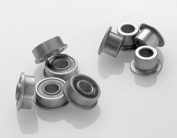
| Figure 1. The heart of the enlarger improvements are provided by four flanged roller bearings and four flanged bronze bushings. These will replace the original plastic bushings on the enlarger to provide much smoother head motion and more stable alignment. See parts list for details. |
Parts List: (Prices updated November 2013)
|
|
|
|
|
|
|
|
|
|
|
|
Replacing the Bearings
The instructions and illustrations that follow show the installation on an
older Omega DII enlarger. This particular enlarger benefits most from
replacement bushings because it lacks a lift crank and must be pushed or pulled
to the desired height. The parts listed here are for a 3/8" diameter bushing
shaft, so measure yours to be sure to this procedure is compatible with your
enlarger.
Find a well-lit area on which to place the enlarger. You will be working mostly on the rear of the enlarger so ensure that you have access to the back. Remove the enlarging lens and lensboard from the enlarger head for safekeeping. A bump to the enlarging lens could be costly!
Next, support the enlarger head by lowering it onto a sturdy cardboard box and tighten the head lock knob. Once it is supported, detach the lift springs from the hooks at the top of the enlarger. These springs can have considerable tension, so use a tool or hook of some sort to gently retract the steel tape into the housing. I’ve done it by hand before, but have always regretted trying to grip the end tightly enough to prevent sudden retraction.
Without the support springs, the enlarger head could drop under its own weight if not held in place by the box. Note that some Omega D enlargers may have a different spring mounting arrangements than shown in Figure 2, but the comments still apply. Once the lift springs are retracted you may detach the spring housings to ease subsequent work, although it is not necessary to do so.
 |
| Figure 2. Plastic bushings located in positions marked "Load Bearing" and "Idler" will be replaced using smooth-acting roller bearings and bronze bushings. Before detaching the lift springs from their hooks, support the enlarger head’s weight on a sturdy cardboard box to prevent it from suddenly falling to the bottom position. |
Finally detach the heavy lamphouse from the enlarger by removing the four thumb screws that attach the lift arm linkage to the lamphouse casting. Once the lamphouse is removed, the lightweight remaining parts are easy to work on. Because you will never have better access to the remaining parts, you may want to clean up dust and grime that has accumulated.
The bushings, attached to shafts on the enlarger head, ride against the enlarger rail to guide up/down motion. There are a total of eight bushings that will be replaced. Half of these serve as load bearing bushings that bear the weight of the enlarger head, and the others are idlers that merely prevent derailing if the enlarger is jostled. Figure 2 shows the location of the bushings and identifies which of them are load-bearing. The ball bearings will be mounted on the load bearing shafts to bear the weight, while the bronze bushings will replace the plastic bushings on the idler shafts.
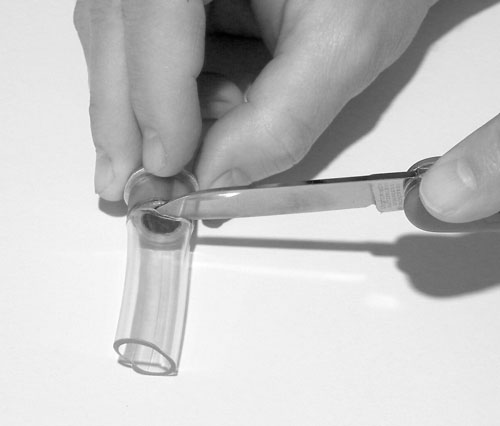
Begin by using a Phillips #2 screwdriver to remove the screws that secure a load-bearing shaft to the head. Once the shaft is removed, the enlarger head could fall if it is not supported by a box of some sort as suggested earlier. When the shaft is removed, slide off the plastic bushings. This shaft may be dirty from years of accumulated grime, so take the opportunity to clean it. You will notice that the shafts that hold the bushings are eccentric - the mounting holes on each end of the shaft are drilled off-center. (See figure 3). This provides the fore/aft alignment of the enlarger when the shaft is rotated during adjustment. It is not an indication of a quality problem.
 |
| Figure 3. A plastic bushing is removed from one end of the shaft. Note that the mounting hole for the shaft is drilled off-center, providing adjustment for enlarger fore/aft alignment. If the mounting screws are damaged or rusty, replace them with hardware store 8-32 x 3/8" screws. Stainless or socket-head screws make for practical, attractive replacements. |
Very old DII enlargers had steel shafts, and if they are rusty, a little sanding makes them smooth again. Test to see if the roller bearing slips onto the shaft. Steel shafts often provide a perfect fit without much work.
Late model DII enlargers had aluminum shafts and the shaft diameter can be a little larger than the hole in the roller bearing. If this is the case, you must sand the shaft at each end where the bearings fit. If you have access to a 3/8" electric drill, you can speed this process by chucking the shaft into the drill and spinning it while holding the sandpaper against it. Don’t overdo it. Remember that a ball bearing’s inner race is supposed to be stationary against the shaft, and a loose fit may invite problems.
With both roller bearings slipped onto the shaft, position the shaft onto the enlarger head support frame and attach the shaft mounting screws into each end. Don’t tighten them just yet - just snug them down. See Figure 4 for proper orientation of the bearing flange. If your original screws are rusted or have damaged screwdriver slots, now is the time to replace them. I ended up replacing the original eight screws with 8-32 x 3/8" button-head socket cap screws. These screws use a 3/32" hex key for tightening. Another good-looking option is stainless-steel Phillips head screws.
Repeat these steps once again to attach roller bearings to the other load bearing shaft.
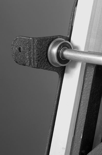 |
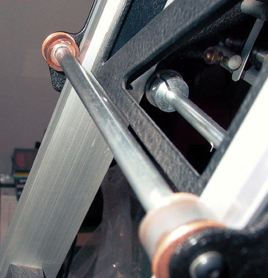
| Figure 4. A roller bearing is shown installed on one of the shafts that support the weight of the enlarger head. The flange should fit between the rail and the frame. This bearing is key to the improvements realized in enlarger motion and alignment stability. |
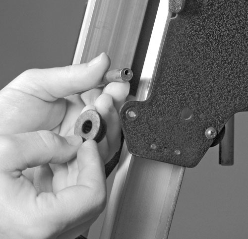
The remaining plastic bushings (idlers) are replaced with bronze bushings that have had a piece of the flexible tubing stretched over the contact surface (see Figure 5). The flexible tubing acts like a "tire" on the bushing serves two purposes: it dampens noise when raising or lowering the enlarger head, and it increases the diameter of the bushings to more closely match the original plastic parts. Without the tubing in place, the diameter of the bronze bushing alone is insufficient to contact the enlarger rails.
The flexible tubing is a very tight fit over the bushing. I inserted needle nose pliers into the tubing and pulled the handles to stretch it first. The stretched tubing will start to return to its original size as soon as the pressure is removed, so work quickly to get it into position. Warm air from a hair dryer may also be used to soften the tubing. After it has been attached, cut the tubing flush with the edge of the bushing. See Figure 5.
 |
| Figure 5. Stretch flexible plastic tubing over the contact surface of the bronze bushings to silence them and to increase their diameter to the desired size. Trim the excess. See text for tips for stretching the tubing over the tight-fitting bushing. |
Remove the shafts one at a time that contain the plastic bushing serving as idlers, and replace the old bushings with the new bronze bushings. Again, some light sanding of the shaft may be necessary to make them fit. Unlike the roller bearings, these bushings must rotate against the shaft so be sure that they turn freely. A little household oil will help. Reattach the shafts to the enlarger and check to see if the flanges are properly positioned in the space between the rail and the enlarger frame.
If you have steel shafts, a light application of household oil on their surface will inhibit further rusting. After replacing all the plastic bushings, loosen the lock knob on the enlarge head, and carefully raise and lower the head by hand to see the head is not "derailed" by out-of-position bearings. Address any problems you find.
Now that the old bushings have been replaced and head movement seems reasonable, it’s time to re-install the lamphouse, lift springs, and lens and then adjust the fore/aft alignment.
Aligning the Enlarger
If you already know how to align your enlarger, you can skip the following
instructions and tackle it in your usual way.
Correct alignment is achieved when the baseboard, the lens, and the negative are all held parallel to each other. Without good alignment, acceptable sharpness across the print is difficult or impossible to achieve. Tools for checking alignment include bubble levels, optical systems consisting of pairs of mirrored surfaces, and laser equipment. The inexpensive bubble level is adequate providing that it is of sufficient quality. I use an Omega alignment tool that utilizes a bubble level mounted in an adjusting base. These can be found pre-owned for low cost.
Ideally the enlarger should be positioned in its working location, but a preliminary alignment may be done in a more accessible location (workbench, table, etc.). If you’ve not aligned an Omega before, doing it first in an easy-to-work location makes a lot of sense.
Begin by leveling the baseboard.. I use pieces of mat board cut to fit under the baseboard feet and check it with a bubble level in both the transverse and long directions.
Rotate the idler bushing shafts so that they are positioned away from the rail and snug the retaining screws to keep them there. This will prevent the idlers from limiting available motion when adjusting the load bearing shafts for alignment.
Next, hold the bubble level against the bottom of the lens barrel to see if it is parallel to the baseboard. The head will probably be tilted forward compared to the baseboard. The off-center locations of the shaft mounting holes allow adjustment of head tilt on Omega enlargers. With the attachment screws on each side of the shaft loosened, insert a hex key or other object into the cross-drilled hole in the center of the shaft and rotate it. Snug the screws a bit to hold position before checking with the bubble level again. Figure 6 shows adjustment of the upper load bearing shaft. Don’t adjust only one shaft to achieve the correct tilt - it’s best to split the adjustment between the upper and lower load bearing shafts. Work between the two to get close, then you can fine tune using just one. After alignment is satisfactory, raise and lower the head to see if it still operates smoothly.
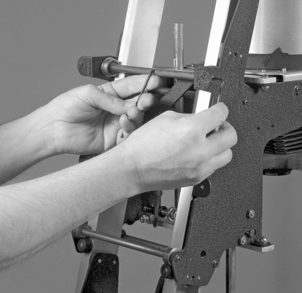 |
| Figure 6. The last step is to realign the enlarger. Rotate the eccentric load bearing shafts to tilt the enlarger head parallel with the baseboard. A good bubble level will suffice for judging parallelism. Depending on the type of screws installed, you may use a screwdriver instead of a hex key to tighten the shaft. The lift springs have been removed in this picture for clarity. |
Once the load bearings are adjusted for correct alignment, rotate the shafts of the idler bushings to place them in close proximity to the enlarger rail. It is not necessary for them to touch throughout the entire range of travel. They may change from lose to tight as the enlarger is operated. If they are too tightly adjusted, you might not be able to adjust enlarger height smoothly at some positions.
Once the fore/aft tilt is correct, check left/right alignment. It shouldn’t have changed but now is the time to check. If it is out of adjustment, focus all the way down to prevent the lens stage from falling to the stops, loosen the screws and nuts holding the bottom focus rail bar (it has the two holes for the focus rails), and tap the bottom focus rail bar left or right with a plastic hammer or screwdriver butt. Tighten when left/right alignment is correct. You may have to adjust focus tension afterwards using the screws that apply pressure to the focus shaft. Use just enough tension to hold focus at all positions.
After the lens stage is parallel to the baseboard, it’s time to check the negative stage. There are four screws and nuts that attach the negative stage platform to the frame. Loosen these to move the platform. I like to start the aligning process with the frame lifted to its topmost position, and lower the appropriate edges to achieve alignment. Check left/right adjustments as well as fore/aft. One common problem when aligning this stage is "potato chip" distortion of the platform. Be gentle and carefully inspect flatness of this stage when aligning. Placing a negative carrier on it provides a reference flat when adjusting.
Conclusions
Replacing the worn bushings in my enlarger has greatly enhanced its action. I
can smoothly nudge the head up or down in fractions of an inch if I want to. I
know also that these stout roller bearings will hold alignment longer than the
original plastic bushings. It’s a satisfying experience knowing that the
enlarger is now built better than when it left the factory.
------
Larry Hamel-Lambert and William Schneider teach photography in the School of Visual Communication at Ohio University.
Addendum 2006 - potential bearing fit issues
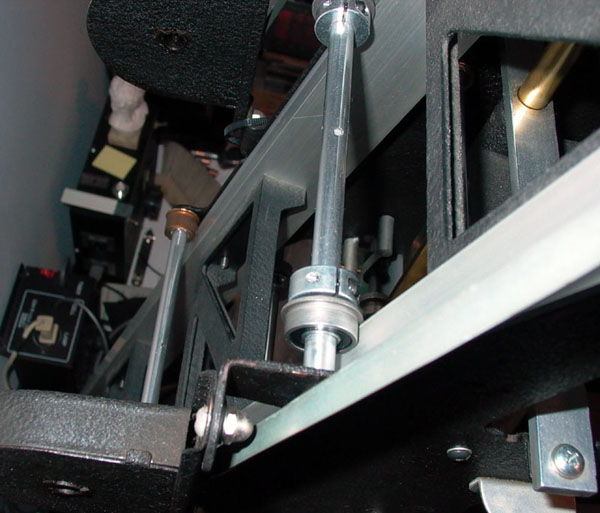
Omega enlargers underwent small changes throughout their production cycle. This may affect how the bearing modification can be installed. One potential pitfall (and workaround) is that the length of the horizontal bearing shafts may be shorter on some enlargers. If that's the case, the protruding roller bearing inner race may prevent proper tightening of the shaft mounting screws because the bearing flanges + extended races become trapped between the upright rails and the enlarger's side panels.
If that's the case, the solution is simple. Move the bearings to the INSIDE of the rails, and use locking shaft collars to keep them in position. Without the shaft collars, the bearings will work their way toward the center of the bearing shaft, and disengage from the uprights.
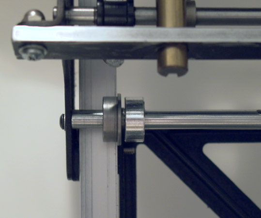
The pictures that follow show how the shaft collars are clamped to the inside of the bearing, maintaining the bearing's position. Note that the bearing flange is reversed from the story above.
There is no drawback to using this workaround, and just to be safe, you may want to buy 4 shaft collars to have on hand for your own project in case they are needed. McMaster-Carr's part number for a 3/8" one-piece clamping shaft collar is 6435K13, and cost $1.71 each at the time of this writing. A more expensive two-piece collar could also be used for convenience, but these will work fine.
The clamping shaft collar is now included in the parts list table at the beginning of the story, but wasn't included in the story published in the magazine.
Because the bronze flanged bearings have no protruding inner race, they can remain located as described in the story. The flange is located between the enlarger side panels and the upright rails as before.
Bill Schneider
October 2006