Zaph Audio ZMV5 Loudspeaker project
|
|
|
| More pictures of the finished project located at the bottom of the page |
Build Log
The following steps outline the design, fabrication, and assembly of this set of Zaph ZMV5 speakers. This project was completed within a few weeks' work beginning in late summer 2009. Eventually, they were given as a gift to a friend who helped my wife through a series of surgeries.
Click any picture to enlarge...
| The Crossover Boards | |
|
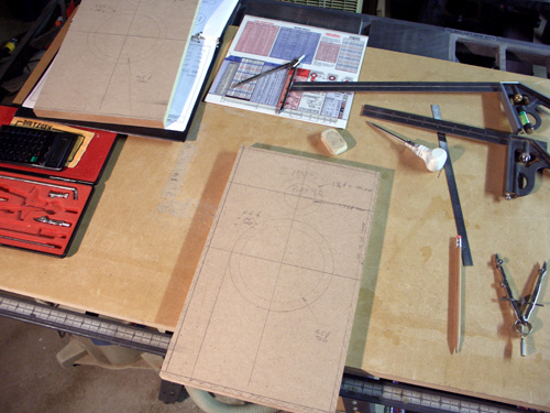
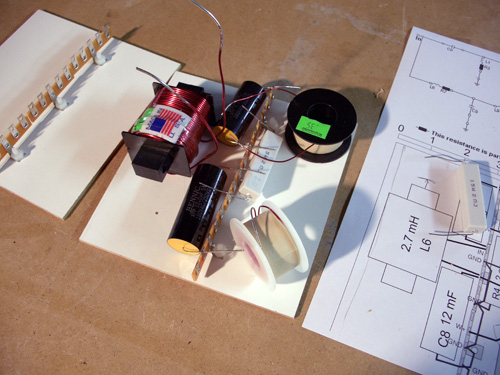
I began this build by planning and
constructing the crossovers first. Components came from both Parts
Express and MCM. I believe the toggle switch that I eventually added
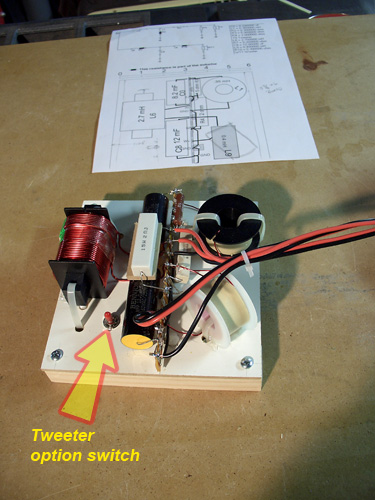
came from Radio Shack. The drawing shows an early plan for the crossover, which the final crossover closely resembles. Later, I added another resistor switched to ground to reduce tweeter level if desired. That provided some tweeter adjustment, although it did mean that the baffle had to be removed to throw the switch. I used some left-over 1/8" thick painted MDF material for the crosover boards. They were mounted to strips of pine using brass threaded inserts and 8-32 screws. I usually rough out the crossover layout using CorelDRAW. I draw an outline of the component to scale, and rearrange them in software to find an efficient layout. Then I print out the layout to scale, and mark the crossover board through the paper template. This makes it easy to do all the hole drilling at one time. In the final photo, the tweeter level switch is called out. The tweeter level is adjusted by switching in another bypass resistor connected to ground. The resistor is the one mounted straddling the two capacitors in the photo. Some of the wiring is underneath the board. The pine mounting strips provide a standoff space under the board for wiring. Someday I might put smaller crossover components under there too to save square inches. |
| Fabricating the Panels and Braces | |
|
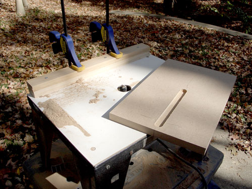
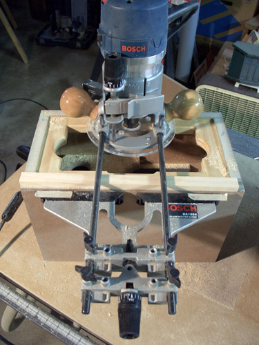
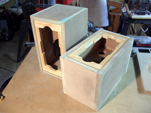
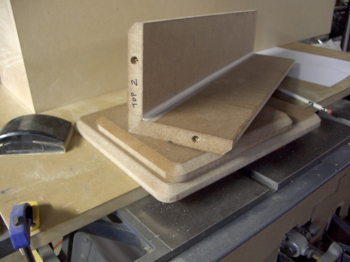
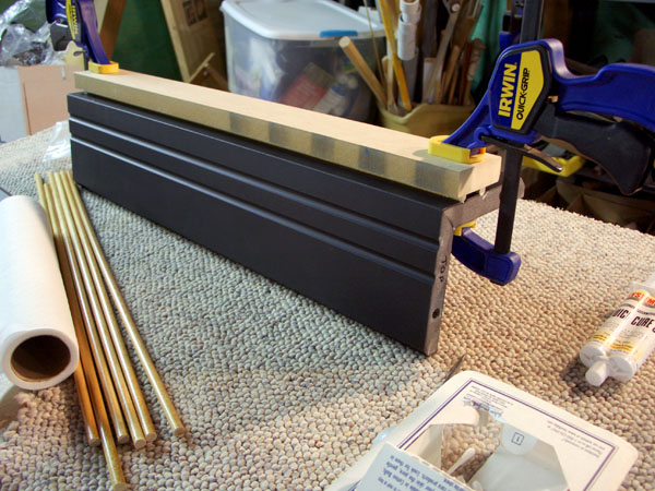
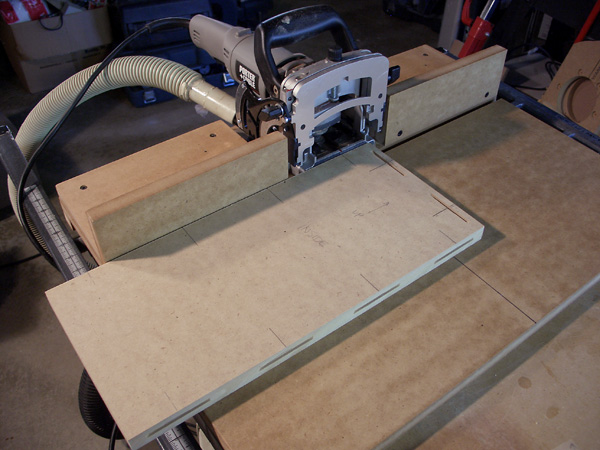
Being small, this build was done with
some leftover MDF from previous projects. It was cut easily on the
tablesaw. I did experiment with a dado cut in the side panels for a brace, something I hadn't done before. It was a "stopped" dado, meaning that it didn't reach the end of the workpiece, or it would have left a gap in the cabinet. I used a small router table for this work, and clamped a piece of wood for a fence. I simply drew a pencil line to indicate the end of cut. This is adequate precision for this work. The braces were fabricated using hole saws for the "air conditioning" holes. The radius at the bottom was necessary to allow space for driver magnets. I cut the corners at the top away to aid assembly, and to provide additional venting. To assemble the cabinet, I used for the first time a biscuit cutter. To cut face slots, I clamped the side panels to a 90-degree jig that I had from an earlier darkroom project. Sometimes it pays to keep junk around. If I were to do this project today, I'd use the biscuit cutting jig that I made later. |
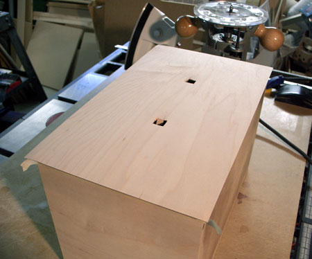
| Assembly | |
|
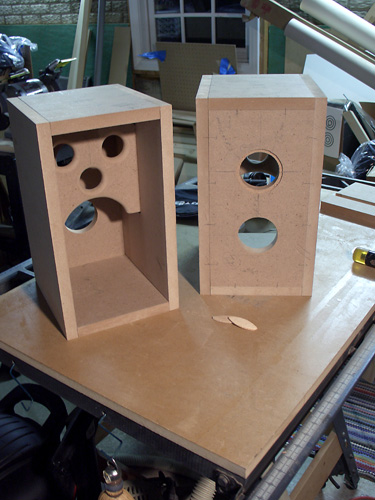
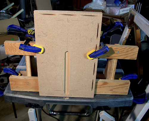
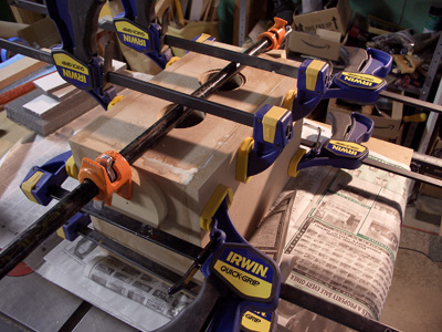
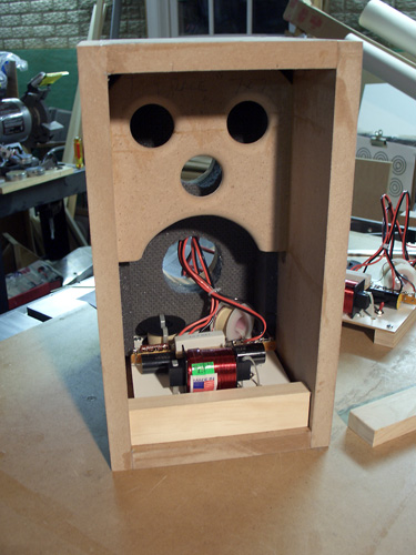
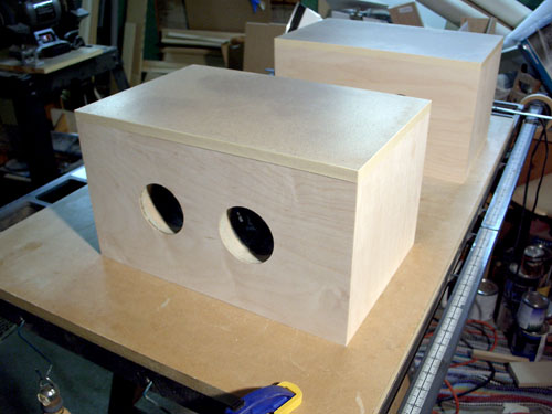
Because I used biscuits, it's easy to
snap together the cabinets sides for a dry fit (top photo). If it goes
together well, it's time to glue it together. I use regular Titebond
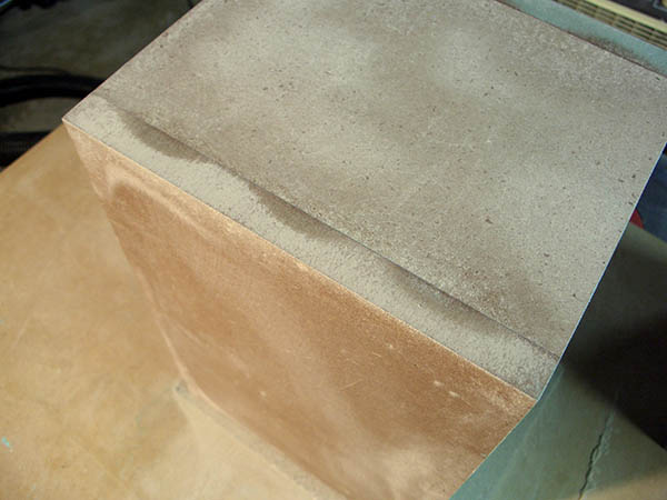
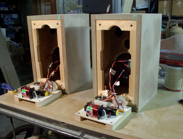
wood glue. Even small cabinets benefit from using many clamps when gluing. You can see that I assembled everything but the baffle in one step. That's part of the joy of working with small cabinets like this one. After the glue dries, it is sandpaper time. Slight mismatches in adjacent sides are take care of here. (Note to self - explore how well a hand plane will do leveling mismatches. The surface isn't quite as smooth, but it's perfect for veneer.) One curious observation is that after light sanding, I could see where the biscuits are under the surface of the MDF. The glue in the slots must shrink, and pull the MDF material down in those areas. After leveling the adjacent panels, I cut a recess for the port tube using a rabbeting bit. Because the port through hole and flange diameter didn't exactly correspond to one of the fixed bearing/bit combinations, I wrapped several layers of electrical tape around the bearing. When cutting the flange recess in this way, it's important to quickly press the bearing surface against the through hole to stop bearing rotation. With all the tape wrapped around it, it's unbalance. When pressed against the through hole, it doesn't rotate. Each wrap of Scotch Super 33+ electrical tape around the bearing O.D. reduces the depth of rabbet by 0.007". I start with more wraps than I need, then unwind the wraps of tape until the flange size is what I need. Because I would need to trim veneer to the same size afterward, I left the tape on the bearing. In hindsight, I should have cut the flange recess AFTER veneering to save time. When the assembly was complete, I glued the crossover mounting rails to the bottom of the cabinet. The crossover boards are still removable because they mount to the rails with machine screws. By this time, I had already adhered sonic barrier foam to the inside rear of the cabinet. Its purpose is to reduce reflected sound inside the cabinet. More would be applied later. In the last picture in this group, I was already testing the fit of a piece of the baffle mounting frame - see Mounting the Baffle to the Cabinet section below. The frame piece is shown in front of the crossover, and was positioned there to check for space.
|
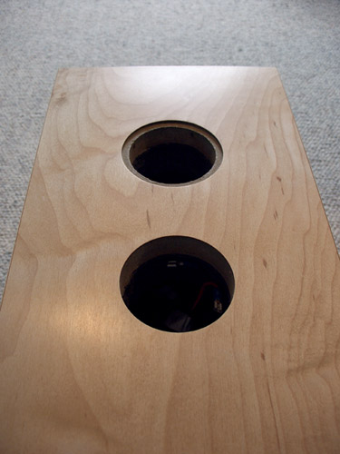
| Baffle Fabrication | |
|
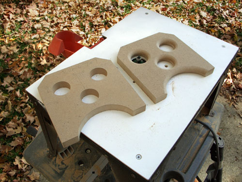
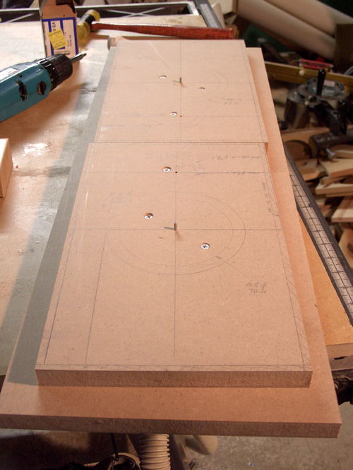
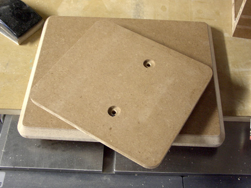
Having a
carefully drawn cut plan on each baffle helps prevent mistakes -
including the most common mistake, forgetting to mirror-image baffles
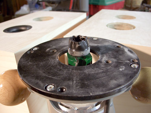
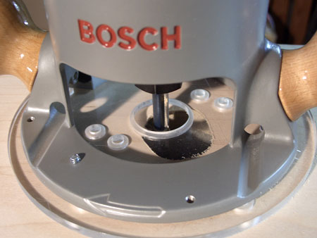
having offset drivers. After drawing the cuts for
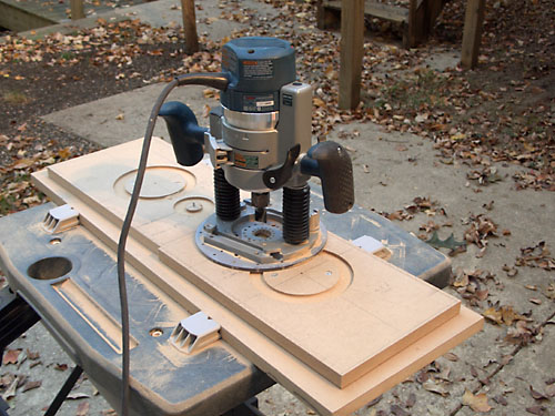
the baffle, I used a Jasper circle routing jig on my Bosch plunge router
to cut the recesses for the drivers and the through-holes on the front
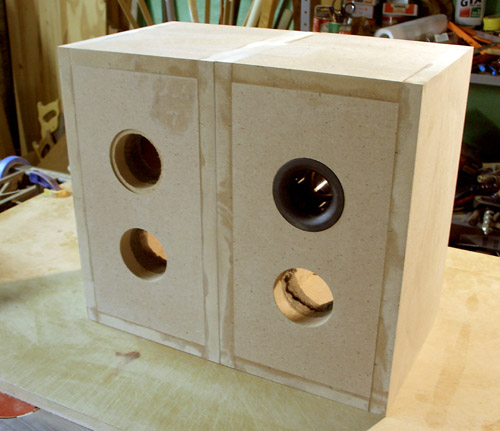
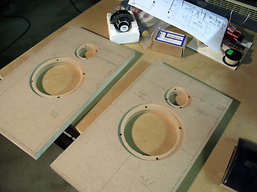
surface. The baffle material was 3/4" thick MDF. I used a 3/4" flat-bottom router bit to cut the recesses for the speaker mounting flanges, then cut the center away with a 1/4" spiral upcut bit. Note the use of a backer board behind the baffles. It serves two purposes - it prevents the bit from cutting into the work table surface, and it also holds the centering pin securely when making the final cut through the baffle. For this build, I used strategically-mounted deck screws to hold the baffle to the backing board. Because these baffles were small, I ganged both of them onto one backer board. |
| Fasteners | |
|
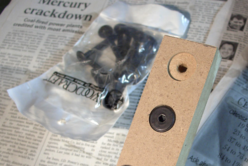
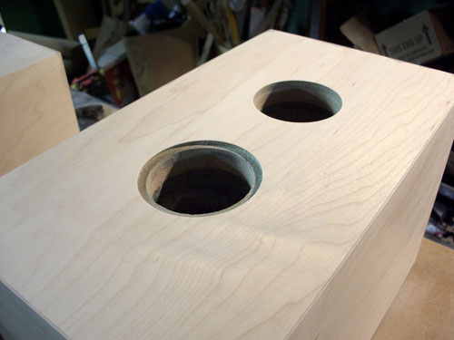
I bought some connector bolts from
Woodcraft to hold the baffle to the cabinet. They are threaded 1/4-20
and have large heads for distributing clamping loads on soft material
like MDF. To ensure a good fit, I made some test cuts on scrap MDF. From
that experiment, I determined the depth and diameter that worked best.
With the drill press already setup for the test cuts, I merely moved the
baffles for cutting. I used a forstner bit for the large diameter
recess, and standard twist drills for the through holes. Because the
forstner leaves a dimple in the center, I cut it first, then drill the
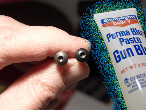
through hole. I bought button head cap screws for mounting the drivers. They threaded into hurricane nuts mounted in the baffle. Unfortunately, the box of screws that I bought was poorly finished. They were even slightly rusty because of the poor oxide finish.. To fix that, I chucked them up in my drill press, used a mild abrasive pad on the screws heads while they turned, then blued them using gun bluing purchased from a sporting goods store. The rusty screws looked top-shelf after that. |
| Mounting the Baffle to the Cabinet | |
|
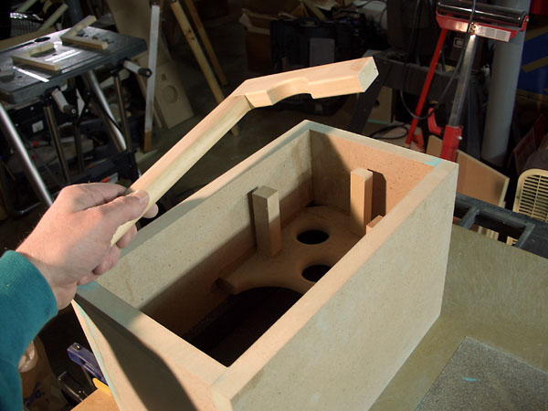
The connector bolts that would hold the
baffle in place needed something to thread into. I fabricated a frame
that fit just inside the cabinet. It was mounted using a slight recess
to allow for gasket material.
Doing this after cabinet glue-up was probably not the best way to do it, but it worked out fine. I knew enough to use a hole saw to provide tweeter clearance at the top. I cut this relief for both top and bottom in anticipation of an "oops" where if I had the relief cut for the top piece, that I'd probably mount it on the bottom. Having both top and bottom the same would prevent that sort of problem. For accurately setting the depth of the frame while gluing, I cut some spacers to length from scrap. They kept the frame from slipping down inside the cabinet until the glue dried, then they were removed. After I glued the frame into position, I found that the woofer frame interfered with the sides. I had to devise a way to cut a relief into the sides. You can see the router guide being put to use to cut the relief. Sometimes mistakes bring out your creative best. Once the inner mounting frame was in place with all mistakes ironed out, I used transfer punches through the baffle holes to mark locations for hurricane nuts. The cabinets were taken to the drill press to accurately drill the mounting holes for the hurricane nuts. I used a drop of Gorilla Glue on each one to make sure it didn't spin later. Once the baffle was screwed into position, I took the assembly outside to flush trim the baffle edge to the cabinet. When flush trimming, I taped a piece of cardboard that was about the thickness of the veneer to the side of the cabinet. This left the baffle a little proud, just enough so that the veneer, when applied later, would be exactly flush with the baffle edge. After flush trimming, I routed a chamfer onto the baffle edge for appearance and to help a bit with diffraction. At this point, it was time to glue the crossover boards to the bottom of the cabinet. The bottom rails are glued, but the machine screws holding the boards to the rails mean that they remain removable for service. |
| First Sound | |
 |
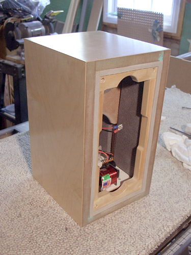
This is the moment everyone anticipates.
Was it worth the effort? Did I do anything wrong?
Those questions get answered now. For some builders, this is the stopping point, and no further finishing takes place. In this photo, the baffle is painted with primer. I use Rustoleum Sandable Automobile Primer because it builds quickly, dries relatively fast, and it sands like a dream. I've tried Krylon primers, and they don't work nearly as well. I like Krylon paints though, and the final baffle paint was a Krylon black semi-flat paint in a rattle can. |
| Veneering | |
|
I have separate
pages for how to veneer with the iron-on yellow glue method.
Basically, I cut a roll of paperbacked veneer into slightly oversized
pieces for each cabinet side. A smooth sponge roller lays down the glue
onto both the back of the veneer and to the cabinet sides.
When the glue is dry, heat from a regular clothes iron applied through a cotton cloth is sufficient to melt the glue for adhesion. A router with a flush trim bit cuts the excess away from the edges. It's very simple and quick. The information linked above also includes how to route the round flange recesses in a veneered cabinet. For this project, I used a roll of Maple veneer purchased from a Woodcraft store. |
| Finishing | |
|
I used Watco Danish oil to provide an
easy-to-apply finish to the speakers. It's a low build finish, and it's
easy to restore if damaged. However it doesn't have the chemical and
water resistance of a hardy polyurethane, but I don't expect that they
will see much abuse. I used 320 grit sandpaper to rub in the first couple of coats of oil so that the sawdust combined with the finish would fill pores and grain. This is a method to obtain a smooth finish quickly. After an application of the oil, I would let it sit for an hour then remove excess with a piece of cotton material from an old T-shirt. Latter applications were applied with just the T-shirt material, not sanded in. I'd always wipe the excess away after a wait. I like working with Maple. The Watco Danish Oil gives it a light amber cast that's very nice. It takes days to finish a speaker using it because of the slow drying time, but the results can be remarkable. After finishing the veneer in the basement, I assembled them again. At this point, I was pondering a number of different colors in addition to black for the baffle. However when my wife suggested that I give them as a gift to a friend for her help, she wanted basic black. I used Krylon semi-flat black spray paint in an aerosol can. (NOTE: I've heard that Krylon black semi-flat black has been discontinued.) It goes on over the Rustoleum sandable automotive primer nicely. See the final photos at the bottom of this page. I also fabricated a grill using Baltic birch plywood for the frame. It was painted black, and had Parts Express black fabric stretched over it. I milled a groove around the periphery of the Baltic birch, and used screen door piping to fasten the fabric to the grill. Neodymium magnets expoxied into recesses in the back of the baffle mated with the connector bolts of the baffle. The strong magnets attracted to the steel connector bolts are enough to hold the baffles into position.
|
| Stands | |
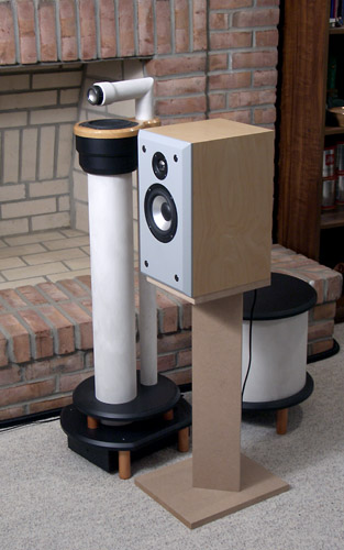
|
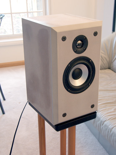
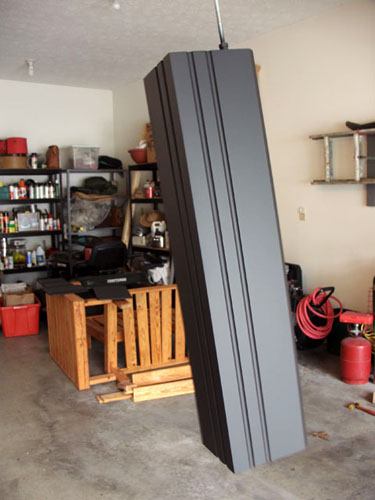
At this point I didn't have any spare
speaker stands, so I cobbled up a set from leftover MDF. The riser was
simply a V shape attached to the horizontal parts using connector bolts
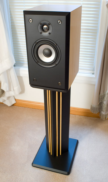
and brass threaded inserts. I assembled them to check fit, and couldn't resist the opportunity to compare them to my Linkwitz Pluto loudspeakers. The are seen side-by-side in the third photo in this section. Over time, I added improvements to the stands to make them more attractive. I rounded the corners of the bases, and chamfered the edges with a 45 degree bit. I eventually milled in some flutes on the front faces of the stand uprights using a router table, and painted them black. I used a different paint on the stands than I did for the speaker baffles, although it's a fairly close match appearance-wise. The stands were painted with General Finishes Lamp Black milk paint, a water based paint that I dilute 16oz paint to 1 oz. distilled water. Diluting it makes it much easier to spray smoothly with my small Lowe's paint gun. The paint sands very well between coats too. The only drawback is that I have to paint in the garage with the door open, and that requires warm weather. Before giving them away as a gift, I took hardwood dowels from Lowe's, applied some light "gunstock" stain and General Finishes Arm-R-Seal semi-gloss, and then epoxied the dowels into the flute recesses. This provided a visual relief from all the dark tones seen from the listener's position. The thin dowels also resembled strings on an instrument, suggesting the musical theme. |
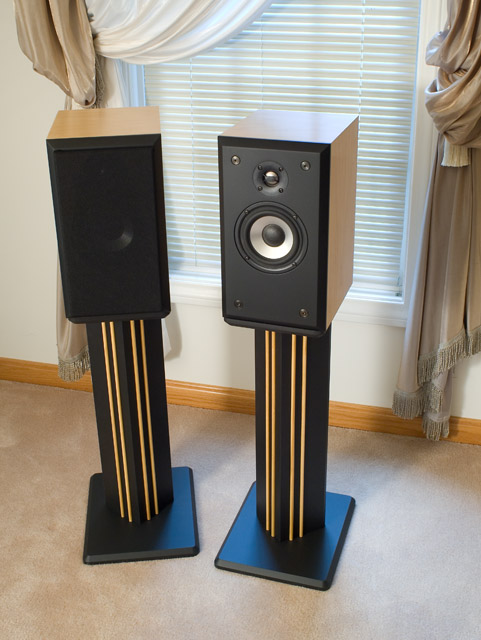
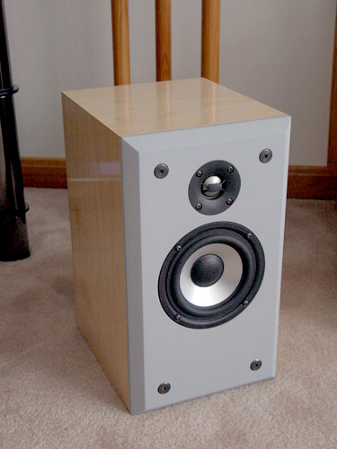
Finished!
Bill Schneider
