
A Round Pluto Plus Subwoofer Project
|
|
|
|||
Construction Notes
The following steps outline the design of a pair of round subwoofers for Linkwitz Pluto loudspeakers using PVC pipe. These were created to match the style of the Plutos which were completed earlier.
The notes below were originally posted to the http://oplug-support.org/ forum. However a server change broke links to all the pictures in the thread. The major points in this project have been reproduced below together with the original pictures.
Click any thumbnail picture below to enlarge...
| Preliminary Ideas | |

|
Sun Nov 11, 2007 I'm going to build round Pluto+ subwoofers. First, I must point out that the idea for a round Pluto+ sub isn't original. Roehrig on this board first posted that he had used round PVC for the sub 'box', (http://www.heinz.cmu.edu/~roehrig/Building Pluto Subwoofers.pdf) and later Wood Artistry offered pre-built subs in a round configuration. |
| Parts and Materials | |
|
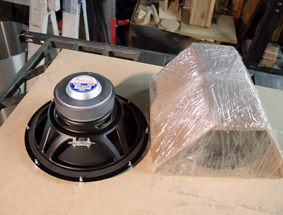
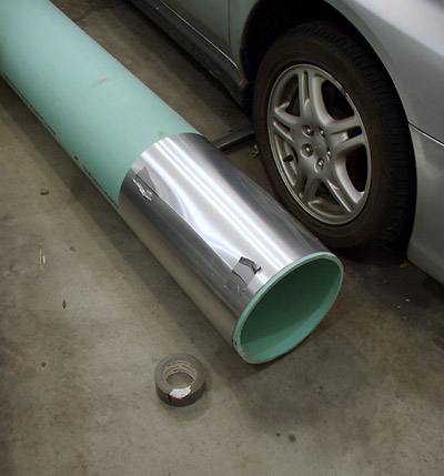
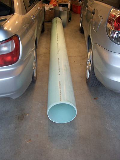
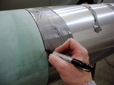
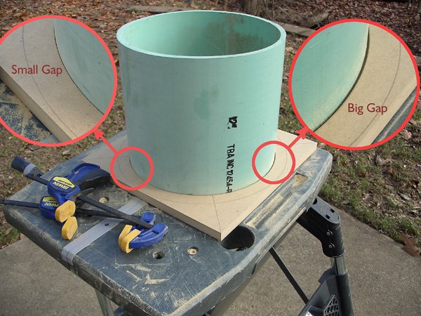
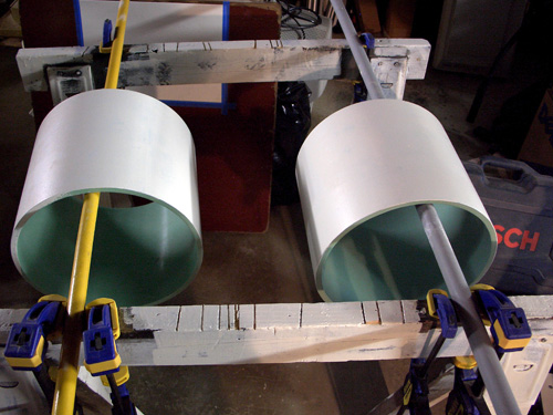
Sun Nov 11, 2007 The 10" Peerless 830668 drivers from Madisound and electronic components from Digikey had arrived by mid-October. Having the actual drivers in hand made planning easier. I've contacted a local plumber/acquaintance about larger schedule 40 PVC. He doesn't have any, but has green PVC sewer line pipe. He brings over a piece of 10" which has only about a 1/4" thick wall. I could live with 1/4" wall, BUT the diameter of the woofer mounting holes is exactly the same as the pipe diameter. There's no way I could even think about screwing into the thin 1/4" wall. The plumber brought over a whopping twelve foot length of 12" diameter green pipe on his next trip. I'm to cut the length I want, then he'll return for the rest. (He offered to sell the entire piece to me, but what would I do with all this?) Navigating the garage is difficult! |
| Cutting the Pipe | |
|
Sun Nov 11, 2007 9:04 am |
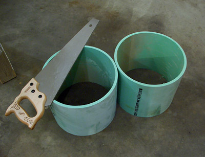
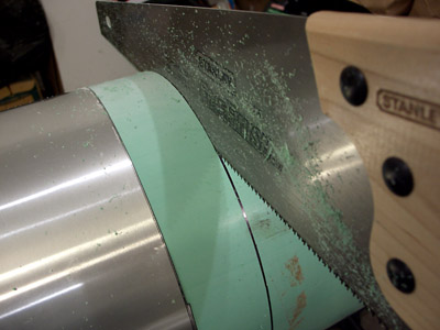
| Completed Cuts | |
|
Sun Nov 11, 2007 9:21 am Ta Da! I've now got a couple of pieces to use. The leftover pipe is still taking up space in the garage and prevents me from fully opening my car door. Hope I don't gain any weight before the plumber fetches the leftover piece. I left a message for him over a week ago. On the electronics front, I've got the boards mostly assembled. There are two capacitors on backorder from Digikey that are due in around November 17th. These boards went together very quickly compared to the Pluto amplifier/eq/xover boards. They have fewer components to solder. The Pluto+ loading chart mentioned a "Jumper-out" that confused me until I consulted the board layout illustration on the last page of the documentation. There it's shown clearly. I was also a little confused between the loading chart and the PLUTO support information page (note 22, 12/21/06) about how to parallel several capacitors. I figured that out (I hope) by consulting the circuit schematic. That information could have been a little clearer for non-experts like me. I guess that's why I'm mentioning this - to help other readers of this board in their own project. |
| Fasteners | |
|
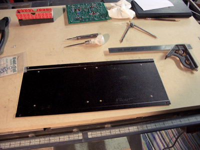
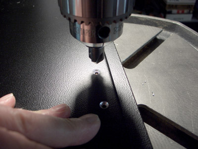
Sun Nov 11, 2007 9:30 am While I'm waiting for the back-ordered capacitors to arrive, I tackle mounting the circuit board in the Hammond case. It doesn't have the nifty polycarbonate top you get when you buy the pre-made parts from Linkwitz Labs, but that's OK. In hindsight I should have marked the screw holes in the case when the PLUTO+ circuit boards were unpopulated and could lay flat against the case. But that's hindsight. I have to now measure the mounting hole pattern, and lay it out on the case bottom plate for drilling. I purchased #4-40 x 3/16 flat head mounting screws from the local mom-and-pop hardware store. First picture: The holes have been drilled. Next: I'm countersinking the holes for the flat-head screws on my drill press... Last: And finally, I test the mounting hole pattern to see if I was sufficiently accurate... Success! |
| Considering Amplifiers | |
|
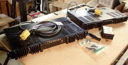
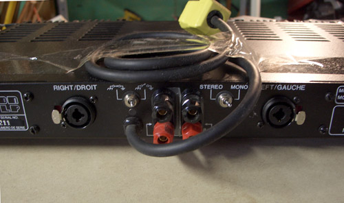
Sun Nov 11, 2007 12:31 pm Among other things, I've been considering amplification for the Pluto+ subwoofers. I'd love to have the ATI 1202 suggested on the Linkwitz site, but that's another $550 to cough up. I'll wait and see if I can muster through with equipment I already have for now unless there's a good reason to switch. Last autumn (2006) I bought a pair of second-hand Bryston 2B amplifiers from a friend who gave me a reasonable deal on them. One is a newer 2B-LP rated at 60 w/channel un-bridged, and the other is the previous model, a plain 2B rated at 50w/channel un-bridged. I bought these with the idea of improving an existing stereo system, but this was before I had heard about the Pluto. These Brystons were outfitted with balanced connectors, and of course the Pluto+ w-asp has RCA unbalanced outputs. I contacted my friend (a former tech at a large TV station) about how to convert RCA to balanced and he gave me this adapter... While using the ATI would be simplest, are there any potential problems to consider about adapting these Brystons for subwoofer use besides that they are not gain matched (I will attempt to measure and make the gain equal)? Will the balanced to unbalanced adapter cause an issue? These amps look to be very well made, with a ground lift switch, bridging switch, and considerable heft. Or should I sell them and just purchase the ATI without monkeying around? The irony is that I paid exactly the price of a new ATI 1202 for these two amps. |
| Refining Plans | |
 |
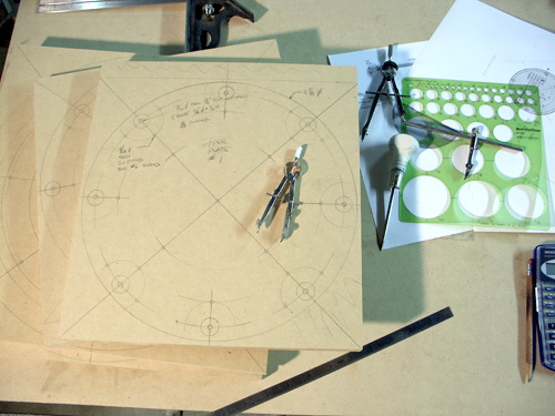
Mon Nov 12, 2007
I Did a scale drawing of how the pipe will be assembled
with the top and bottom plates. Wish I had 14" pipe now! I can make 12"
work, but space around the driver will be very tight for assembly
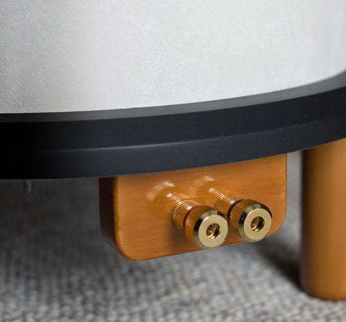
hardware. For instance, I had to drop the binding posts onto a plate
suspended under the enclosure. There simply wasn't enough room to put
them adjacent to the driver. That adds a bit of complexity, but nothing
serious. |
| Fabricating top and bottom plates | |
|
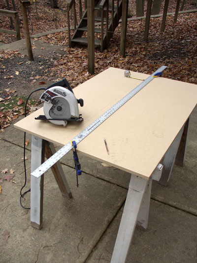
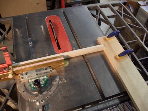
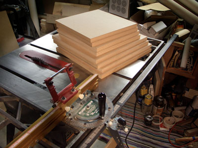
Mon Nov 12, 2007 8:41 pm Because it was a holiday today, I tried to make huge progress with these subs. I'm going to have to settle for modest progress. I went to Lowes and bought a ~4x8 foot sheet of 3/4" MDF. Lowes cut it into a 3x4 foot piece, a 3x5 foot piece, and a strip about a foot wide. This fits into my Toyota Matrix nicely. Back home, I set up the saw horses out back to cut down the 3x4 sheet. Because I will need four 14.5" diameter pieces, I make two cuts with a circular saw that provide two strips 14.75"x 4 feet long. I use a thick rule to provide the cutting guide - it gets securely clamped to the MDF at each end for the cut. I take the 14.75" wide pieces indoors to the table saw to make 14.75" square panels. The 1-foot wide strip is diced into 12" square pieces that will be routed to the appropriate diameter to fit inside the pipe. I like to route these shapes round outdoors because of the sawdust. However, it's dark by the time I get home and that will make it difficult to work. Because I spray paint in the garage, I might not be able to spray paint the top and bottom plates when it's too cool. And it's definitely cool now. I might just take the 3x5 foot leftover piece to quickly make a square SL-style box to tide me over while I take my time with this round enclosure. At least this way I can listen to a Pluto+ while the final enclosures are being built. That's a problem too. I already find myself listening to the Plutos instead of doing work. Having the Pluto+ functional will make it even more tempting to listen instead of cutting/painting/routing, etc. |
| Electrical Work | |
|
|
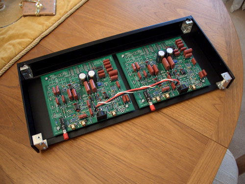
Fri Nov 16, 2007 10:40 am The backordered parts from Digikey arrived last night, and I completed the W-ASP (Woofer-Analog Signal Processor) boards. Wish I had front mounted the LEDs. Because the Hammond case has a metal top panel (and not clear polycarbonate like the Linkwitz pre-built units), I will have to leave the top off while I set it up. Still, once set, it should remain so for a long time. Minor inconvenience. It passed the LED-on test, the +/-12v measurement test, so I inserted the op-amps for a final 'smoke' test. Everything seems OK for now. BTW, that outboard power supply is a hefty unit! Having it completed this far makes me realize that if the drivers were mounted in their enclosure, I could start listening. The round enclosures will take some time to complete because of uncertain weather for painting and routing outdoors. I still might assemble some quicky, unpainted square boxes out of the left-over MDF. That way I can listen while I take my time with the round enclosures. That will reduce the 'haste' incentive. We'll see. |
| Plan Refinements | |
|
|
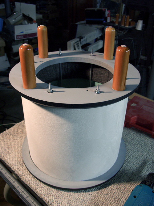
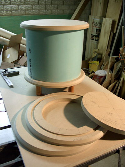
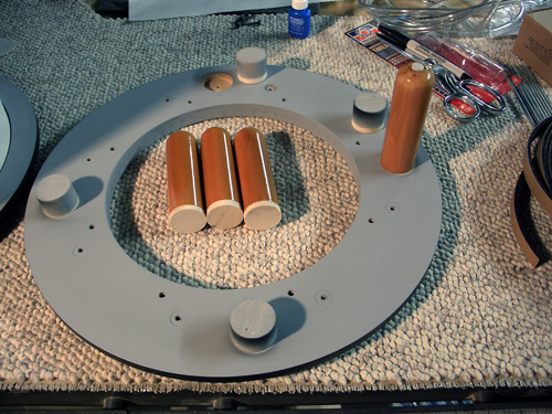
Sun Nov 18, 2007 4:23 pm I haven't been making sawdust today, but making eraser dust doing detailed parts drawings. Some conclusions: A) I don't need the 3/4" inner rings on the bottom end using an all-thread faster system. I could have cut the pipe 3/4" shorter to achieve the same volume. I can still build it with the rings, but I might omit this piece, and add another piece of easily-shaped wood inside to occupy the missing volume (~80 cubic in.). That would save the time consuming fabrication of the two rings. B) This would have been a lot easier with 14" diameter pipe! The space between the speaker OD and the pipe ID is small, and the early plans I showed early in this thread must be changed. The threaded fasteners on each end of the all-thread rod interfere with either the pipe wall on the top, or the speaker OD on the bottom. There are two solutions - one is to have the all-thread positioned in the speaker mount hole positions, and then thread nuts to hold the speaker and everything together. This means juggling lots of loose parts during assembly, with rod ends pointing at the speaker cone, etc. I believe this could be disastrous. The next solution is to angle the all-thread rod to avoid the tight spots. I would mount it well inside the pipe wall at the top, and angle it out so that the exit at the bottom clears the speaker OD nicely. A few degrees tilt would do. It's an inelegant engineering solution, but it's straightforward to do. Now someone will say "..why not just drive screws in through the sides of the pipe to attach the inner end pieces?" Well, I'd have to fill and paint the screw holes, and that means a two tone paint job (like my Plutos) would have to be accomplished with masking, etc. on an assembled enclosure. That's not an elegant solution either. |
| Updated Drawing | |

|
Tue Nov 20, 2007 12:09 pm Maybe it's time to post an updated drawing... This design should have much less baffle area (secondary sound radiation area) than the 14" square SL-specified box. I calculated the baffle area for the standard design to be 111 square inches (14" squared, minus the area contained by the OD of the woofer). The round baffle in the design above will have only 37 square inches of area (discounting the area outside the vertical pipe walls). Also because the mount holes for the woofer are closer to vertical pipe walls, it should be stiffer too. Because of the small, stiff area presented by the baffle ring, I'm not too concerned about baffle vibration. It's better in that regard than the original. The design above should use a shorter pipe than the one that I had cut already, but I can add some extra material at the top to occupy the additional volume created by the design change. If I were cutting new pipe, it would be 9.95" long instead of the 10.7" pieces I have now. Drilling the angled holes will be straightforward too. |
| Prepping MDF for Fabrication | |
 |
Sat Nov 24, 2007 2:27 pm A minor head cold last week and then poor weather on Wednesday conspired to cancel my travel plans for Thanksgiving. I did however get a little more work done. I'm almost ready to make sawdust, but I want to double check cutting plans first. I've made cut diagrams and notations on the pieces of MDF that I'll be using. I purchased a needed 1/2" flat-bottom router bit, but I still need to order some fasteners and all-thread rods from McMaster-Carr. Sawdust soon, I promise. |
| Routing Begins | |
|
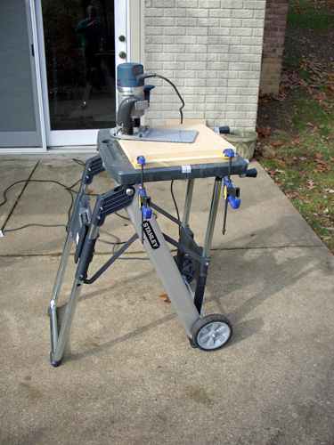
Tue Nov 27, 2007
I've made a little progress recently. I got the grooves
cut into the plates for holding the pipe. Here's a shot of the work area
outdoors. I can make progress as long as the weather holds out. |
| Detailed Parts Drawings | |
|
Tue Nov 27, 2007 3:27 pm For anyone else contemplating this method of Pluto+ construction, here are the fabrication plans for the components. All these pieces are made from 3/4-inch MDF purchased from a Lowe's store.
Pictures are in the following order... |
| Routing the Top and Bottom Plates | |
|
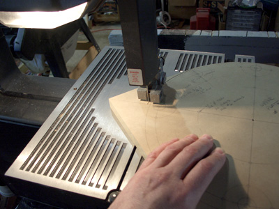
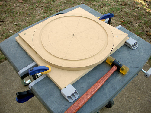
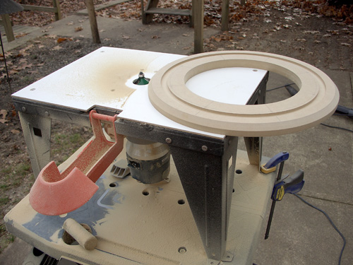
Tue Nov 27, 2007 7:43 pm I made a little more progress, but darkness halted things tonight. I tried something new today. Instead of making the round shapes entirely with the router (slow, and eats 1/4" spiral upcut bits), I decided to rough-cut the circular shapes on a second-hand bandsaw that my father gave to me last summer. It vibrates so much that sometimes it's difficult to see where you're cutting. Still, it slices the MDF like butter. I tried to leave about 1/8" around the periphery so the router could clean up the OD. The second photo shows the rough-cut parts fresh from the bandsaw... That went very quickly and easily. It was dusk, so I tied to do as much as possible before darkness halted work. I experimented with different bits for the router with the circle guide. The 1/4" spiral upcut bit cut slowly, and left very small chatter marks on the OD of the parts. Since I was cutting the inside part that will never be seen in the completed Pluto+, I fetched my 1/2" diameter straight bit and gave it a try. WOW! I had to change the pivot hole setting on the Jasper to accommodate the larger bit, but wow, did it ever slice through the MDF! The cut was also much smoother. I've discovered a better, faster way to make these disks! The last photo shows the last part being routed - a top plate - after darkness fell and just before I stopped working. If the weather holds tomorrow, I'll finish the remaining 3 pieces and chamfer the edges with the 45 degree edge trimming bit. This is easy! Finishing will be more difficult. |
| Routing Driver Hole and Dry Fit | |
|
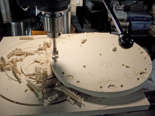
Wed Nov 28, 2007 5:11 pm Most of the outdoors routing is done. I finished trimming the disks remaining from last night, and I was able to cut the driver holes, chamfer the edges of the disks to match my Pluto base, and did a preliminary stack-up of the parts. To cut the speaker hole, I used the scrap cutoffs from the jig sawing step to capture the disk so the outside wouldn't move. The center was pinned through to the piece of scrap underneath. It could only rotate once cut free from the disk. Then I fetched my cheapie Sears router table to cut the 45 degree chamfer around the edges of the four external disks. Piece of cake. Here's a shot of the bottom plate with the driver hole cut and the edge chamfered... I took the parts inside, found some left-over legs from the Pluto project, and loosely stacked things together to see how it fits and to get a sense of the appearance... It's going together quickly, but I'm sure finishing will slow me down. It's been too chilly to paint in the garage. On another note, I ordered the all-thread, some felt, #8-32 screws and locknuts from McMaster Carr last evening, and the box arrived this afternoon via UPS ground. Shipping took LESS THAN 24 hours. That boggled my mind! Another useful discovery -- a leaf blower REALLY cleans up the router dust from the tools and surrounding area. |
| Dry Fit In Place | |
|
Thu Nov 29, 2007 9:47 am Here's another view of the stacked parts - this time close to the PLUTO to judge scale. I worked till late last night, and discovered that I didn't have the proper wrench to adjust the tilt of my drill press table (it takes a 23mm, and I can't find one around here). I want to be able to use the tilting work table feature to drill the 1-1/2 degree holes it takes for this design. I could just use an 0.30 shim properly placed on the far side of the piece being drilled, but I might as well get the tool to let me adjust the drill press table easily in the future. Very late, I made my first mistake. I countersunk the 25 screw holes on each inside plate on the wrong side. Thankfully, it's an inside part if I choose to ignore the mistake - the countersinks will be on the glued surface. I can make new countersinks on the proper side. This mistake will not be visible, and will not cause any structural problem. However I changed the part drawing to specifically point out that the countersinks should be OPPOSITE the hurricane nut counterbores. I also discovered that the dowel rod that I had purchased from Lowes (1-1/8" diameter) is smaller than the legs on the existing Plutos. I will return to Lowes to see if they have the 3' lengths of 1-1/4 inch that I need to match the existing Pluto legs. They DO have very long (8 or 10 feet) handrail dowel, but that stuff is slightly oversized and requires a ton of sanding to fit into the counterbore. I learned that lesson making speaker stands once, and now I avoid the long stock for that reason. |
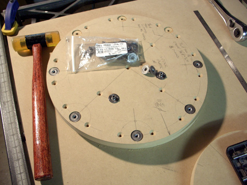
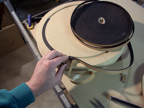
| Threaded Hurricane Nuts and Gasket | |
|
Thu Nov 29, 2007 8:56 pm I got more done today. I found a 23mm socket to adjust the drill press table at Lowes together with the proper 1-1/4" diameter poplar dowels for the legs. I tilted the drill press table 1-1/2 degrees (it isn't much!). I drilled and counterbored the holes that needed it. Here's a shot of the counterbores being drilled for the Hurricane nut flange clearance. Because this surface gets glued and screwed to the top plate, everything must be flush. After drilling and counterboring these holes on both inner plates, I inserted the #8-32 Hurricane nuts with a light tap of the hammer. Do you think I've got enough screw holes to firmly clamp this thing to the top plate when glued? :lol: That's a classic case of overkill. Oh well. Because glue may drip into the threads of the Hurricane nuts, I attached self-adhesive dots. That should keep the glue out of the threads. The gasket was fitted into the groove of the top plate. It fit perfectly. I have to do that now before gluing, because the inner plate will slightly overhang the groove and gasket, making it more difficult later on. I'm looking at a pause in the work for a few days. Back with more pix and info soon. |
| Pre-Finishing Starts | |
|
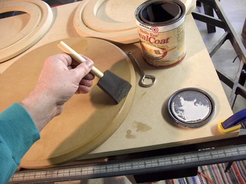
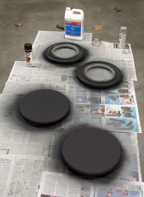
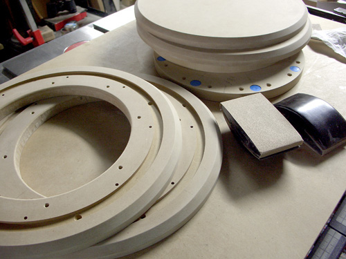
Mon Dec 03, 2007 8:18 pm I got a little more done. One thing that I'm going to change is the leg length to match the existing Plutos. That way the bottom plate will align with the lowest platform on my Plutos. That change is now reflected in the assembly drawing on page two of this thread. I used Zinsser Bulls Eye Seal Coat (a dewaxed shellac solution) sanding sealer on the MDF so that it will sand easier and, most importantly, take spray primer nicely. Unsealed MDF really sucks in the primer and many, many coats are required to achieve a smooth finish. The sanding sealer is easy to apply, and makes subsequent finishing go much faster. It dried for a couple of days before I was able to do anything more. Today I got around to sanding the pieces smooth - especially the cut edges of the MDF. Even the smooth-cutting 1/2" diameter router bit left a little chatter to clean up. The driver recess, cut with the 1/4" upcut spiral bit was REALLY undulated with chatter marks, but it doesn't matter there. I'll never use another 1/4" spiral bit for finish work! It requires too much cleaning up. The second picture shows the parts freshly sanded after the Seal Coat shellac dried... I did some minor chamfering/rounding of the edges so that they wouldn't be knife-sharp. The weather is awful here, and I'm afraid that spray painting in the garage will be impossible until the weather warms. I can still paint the pipe sections because that's applied with a roller and brush. No overspray to worry about, and few fumes. |
| Gluing Top and Planned Finish | |
|
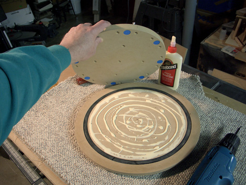
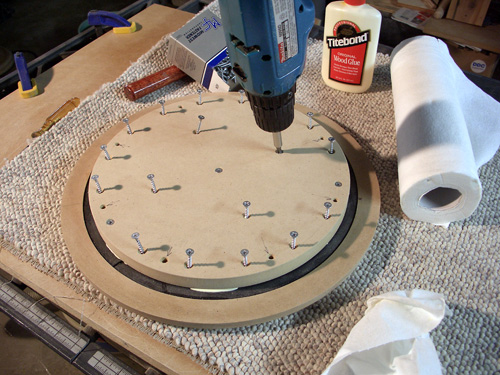
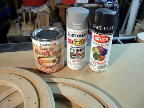
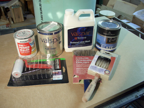
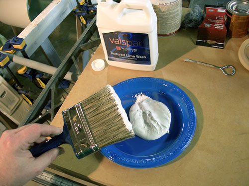
Tue Dec 04, 2007 6:23 pm I glued the top plate and the inner plate together today. That permanently (for better or for worse) encapsulates the Hurricane nuts. Plenty of glue was used, and I used a BUNCH of screws to clamp the two parts together. The electric drill with a Phillips head driver made short work out of the clamping screws. Wipe up the squeeze-out, and now wait a day for it to dry. If anyone is interested in how I'm going to finish these, I've got some pictures of the finishes I used for my Plutos. I used Zinsser Bulls Eye Seal Coat sanding sealer as a base coat for the MDF. Otherwise, it becomes very time consuming to primer and paint because of the absorbancy of the MDF. I sand that well, and then spray Rustoleum automotive primer (wet sandable). I'll spray, then sand, then spray, ...until I get a good smooth surface in glancing light. It has to be 50 degrees F to use the primer, and it barely broke freezing here today. After the primer is satisfactory, I use Krylon semi-flat black (may be discontinued now), about 2 or 3 coats, for the final finish. I don't own fancy spray equipment, as you can see. The spray can finishes aren't as durable, but it will be OK for this project. The textured surface with which I have painted my Plutos will be used also on the subs. I start by sanding the PVC, then roll on a coat or two of Zinsser BIN primer. It's alcohol based, and seems to stick very well to PVC. It dries quickly too, with pleasant odors. Then I use ordinary latex paint for an undercoat for the textured lime wash. I've chosen an antique stone color for this work (left over from my Plutos). This gets rolled on also. Being water-based, latex is easy to work with. Then I use a color washing brush to apply the lime wash in a spiral pattern around the round tube. It's thick and pasty in texture, so I merely glob a bunch out on a paper plate, and fill my brush from that. I let it dry a couple of days. No odor, so it can be done in the basement. To protect the somewhat delicate lime wash surface, I apply a clear latex glaze afterwards. I just brush it on. Coating the PVC is relatively easy using rollers and brushes. The spray paints for the MDF require the garage and warmer temperatures. |
| Wooden Leg Finish | |

|
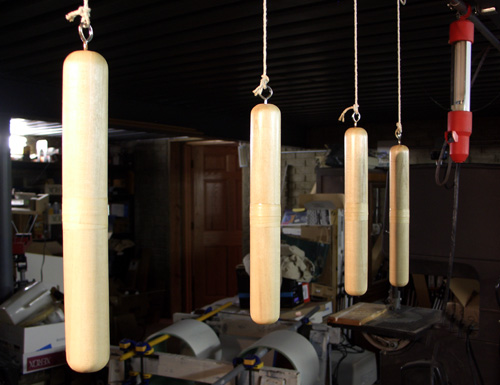
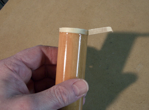
Wed Dec 05, 2007 6:16 pm I forgot to mention the finishing materials for the wooden legs. They are an accent color in an otherwise b/w speaker. The Plutos used the same theme. I coat the dowels with Minwax semi-gloss polyurethane several times before I stain. This is not the usual way that it's done, but through trial and error, I discovered that this works for me. When applied over the poly, the stain will behave oddly at first (much like oil and water), but then spreads out thinly to provide a very even tint. The stain I used for the Plutos, and will use also for the Pluto+ is Minwax 'gunstock' color. After I stain, I again use the polyurethane for a couple more coats over the stain. By then, the semi-gloss has built up to a near-glossy surface as you can see in the photo above. |
| Leg Fabrication and PVC Primed | |
|
Wed Dec 05, 2007 6:28 pm I cut the legs for the Pluto+ subs today. After cutting, I rounded the ends on the router table, and put the first coat of polyurethane on them. I just use a piece of an old t-shirt to wipe it on. I cut them a little more than twice as long as they will be - each piece is two legs. I put masking tape around the center so that the finish doesn't build up there. I will cut them apart after they are completely finished. By doing it this way, the tape when removed will expose bare wood for inserting into the counterbore. The legs will not fit into the counterbore if the diameter increases with layers of finish. The freshly cut end plus the unfinished band previously covered by the masking tape can be glued into the bottom plate and provide a good surface for the glue. I also use a large file to smooth the cut ends of the PVC, and then rolled on the BIN primer. |
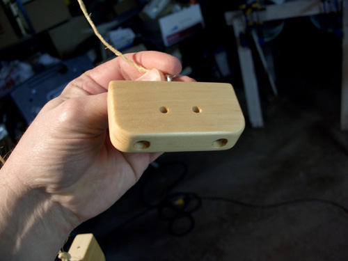
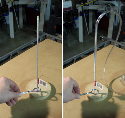
| Hurricane Nut Insertion, Binding Post Fab, and a "Ting" Experiment | |

|
Sat Dec 08, 2007 6:42 pm I haven't been able to paint the MDF pieces, and I haven't done anything more with the pipe sections. There are a couple of imperfections in the surface that I might Bondo before going further. I first thought (wishful thinking at work) that enough coats of paint and the textured lime wash finish might hide them, but I've got the time to do it right. Bondo's in my near future. I decided to use a Forstner bit to put shallow counterbores were the Hurricane nuts will be located for the Peerless driver. Don't ask why - it isn't required - but I felt that I had to be doing something while I wait for better weather. I also gave the MDF another thin coat of Bullseye Seal Coat (wipe on this time, no brush), and sanded that smooth after it dried. The MDF feels like granite now with the hardened surface and smoothness. I also fabricated the binding post mounts and gave them a coat of poly. After a couple more coats, they will be stained to match the legs. While I wait for the weather to break, I mull over the design in my head. I'm using all-thread rods (8 per sub), and I wondered if they would ring at certain frequencies. I did a 'ting' test with a 1 foot section of it, and indeed it sounded like struck metal. I went to the hardware store and bought enough 3/16 id x 5/16 od flexible tubing to slip over each section of the all-thread. It's a loose fit, but it's bound to touch the all-thread in several places - enough to dampen the sound. The 'ting' test It did indeed damp the metal sound a BUNCH. What once rang, now just went 'thump'. Looks like I'm going to dress up the all-thread with transparent clothing. Each rod will have a length slipped over it. I also have some felt from McMaster Carr for sticking to the inside bottom surface of the pipe. It will touch the all-thread. That should provided even more damping. See the assembly drawing on page 2 of this thread for the location of the felt. Oh, yes, the plumber picked up the remaining length of 12" pipe. I can get around my garage once again. |
| Painting Inquiries | |
|
|
Mon Dec 10, 2007 4:21 pm The auto body shop shot down one finishing idea... Because recent weather has been too cool and damp to use spray paint in my garage, I took the top and bottom plate assemblies to an automotive painter to see if they would primer them for a reasonable fee. The manager ran his hand over the pieces, and said that they might be too smooth to paint. He took one part into the back room to consult a painter. The painter then came into the office and said that the 2-part primer they use might interact with the existing surface of the parts. A rep from their paint supplier was there too, and he said that the primer they use is chemically reactive with the steel of automotive body parts, and echoed the opinion that there could be an adverse reaction (bubbling, etc.). He described the epoxy as having a mild etching action on steel. They asked if I had a sample to test, but of course I didn't foresee that request. It was apparent that they were reluctant to take on this job on a non-familiar substrate. I took the parts back home, and will await better weather. I did manage to get the latex base coat ("antique stone" color) rolled onto the pipe sections. Looks nice. The textured lime wash will follow that. Finishing of the wooden legs and binding post blocks is still underway, and I've got about 4 coats of poly on them so far. Staining will happen within a few days, then a couple more coats of poly before I'm done. After they are done, I can cut the leg sections apart on my table saw. I am strongly considering just putting it all together as-is to listen, and re-commence finishing in spring. The design is such that I can disassemble all parts for repairs or refinishing later. Doggone weather! |
| Applying Primer and Lime Wash | |

|
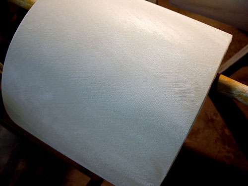
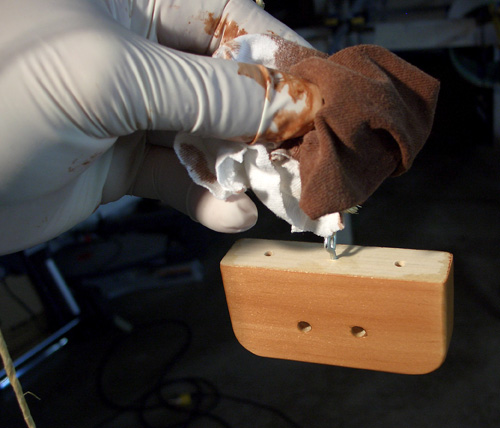
Tue Dec 11, 2007 7:42 pm Well, what do you know? It got up to 65 degrees F today! I took advantage of the weather to put the first coat of primer on the plate assemblies. It's not summertime, so it's still drying (slowly) in the garage tonight. The weather may worsen again tomorrow, so that will probably be all I can do. I'll assemble the Pluto+ subwoofers as-is once the legs are finished and enjoy listening to them until late spring or early summer. I continued work in the basement on the parts that I could finish without spray painting. In particular, I applied the lime wash to the pipes to match my Pluto pipe finish. The second picture shows what lime wash looks like on the special brush for it. I used a very soft bristle color-washing brush that I purchased at Lowe's in the faux finishing section to apply the lime wash. During brushing, lime wash thickens considerably. That makes for interesting "artistic" textures on the pipe. Some of the warm-toned latex shows through in random areas, creating a visual depth. Here's what one pipe looked like after the application of lime wash... I also applied stain to the legs and to the binding post blocks. I use a piece of an old t-shirt to apply the stain. It applies oddly over the polyurethane finish, but self-levels to minimize brush marks within a few minutes. It is important not to revisit a piece that you have already coated. That's another thing that I learned the hard way -- apply it, and leave it alone. Any attempt to brush-up the finish will remove stain once it's been in place for a few minutes. These parts will get a couple coats of polyurethane after the stain dries. If a piece needs more stain, it must be applied after a couple coats of poly, and not over the original stain. I was VERY thankful for this unusual warm spell today. . |
| Painting the Top and Bottom | |
|
Wed Dec 12, 2007 3:13 pm I took the plunge and sprayed on one coat of black on my way out of the door at 6 am this morning. The wind was blowing (see leaves blown into the garage in the picture), so I had to close the garage door and spray in an unventilated area. Gag! When I returned home, I was put into the doghouse by she-who-must-be-obeyed for making the house smell bad. Absolutely no more spray painting until spring when I can open the garage door for fresh air. The finish isn't top notch, but it's OK. I am afraid that some little pieces of wind-borne debris may have found their way into the paint. The surface of the top plates is also a little uneven in texture when viewed in glancing light. I guess that provides some motivation to complete the finishing job next spring, but at least I'll be 90% of the way there. I am going to put a transparent glaze over the lime wash to protect the finish on the pipes, wipe on another coat of poly on the legs, and I should be able to assemble them this weekend if everything else goes well. My fingers are crossed! |
| Tweaking Enclosure Volume and Adding a Protective Glaze Coating | |
|
|
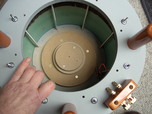
Thu Dec 13, 2007
I did a little more work leading up
to assembly. First, I added additional material to occupy the extra
volume left by my generous cut of the PVC pipe. I needed to reduce
volume by 80 cubic inches because of the extra 3/4" length I cut my
pipe. (I had cut it thinking that I'd use another ring of MDF inside to
which the driver would be mounted. I omitted that ring in a subsequent
design iteration.) |
| Assembly | |
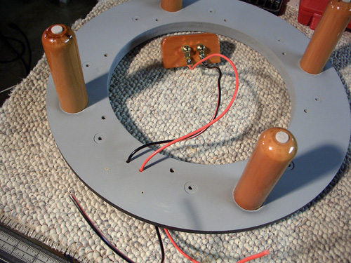
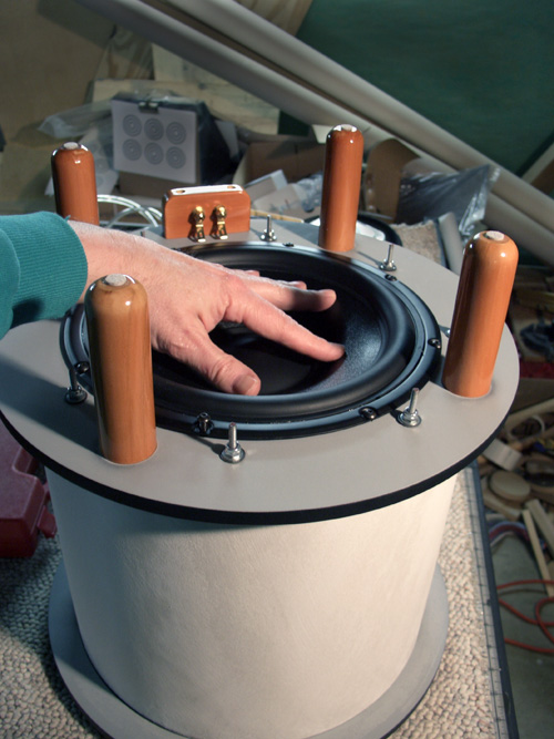
| Sun Dec 16, 2007 11:44 am On a happy note, I assembled both Pluto+ subs yesterday. It went very smoothly. Both enclosures were VERY airtight - I could barely push the cone of the driver in at all because of the trapped air inside. To ensure that I had a "pinhole", I drilled the holes for the speaker leads slightly oversized. The insulation measured 0.105 inch diameter, so I drilled a 0.125 hole. The extra 0.020 inch should provide slow leakage to equalize atmospheric pressure changes. I made plenty of assembly photos and I'll get them edited and posted here soon. I haven't heard the speakers yet, so that will be top priority today. I tested the drivers to make sure that the polarity was as marked. The AA battery test ensures that the drivers push the cones outward when the + DC terminal of the battery is connected to the red binding post |
|
| Leg Work | |

|
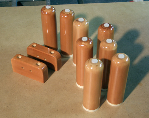
Sun Dec 16, 2007 3:57 pm Here are a few shots of the final steps for my Pluto+ subs. First, I cut the finished legs to length on my table saw. This took less than 5 minutes. The white cardboard shown above was merely to prevent scratching of the finished legs as they were pushed along the saw's table. Afterward, I removed the masking tape that prevented finish from building up on the part of the leg that fit into the bottom plate counterbore. This took longer than cutting the legs. Fiddly work! Here are all the finished parts awaiting assembly... You'll notice that I put on self-adhesive felt pads on the leg bottoms -- just a little touch. I removed the stub legs that I put in place earlier (to prevent finish build up and to elevate the bottom plate from the floor when painting), and then attached the finished legs. One one sub I attached the binding post plate before I did more, and this worked best. The other sub had the bottom plate attached first, then the binding post plate attached afterward. That was more trouble. This shows the new legs mounted securely (I decided not to use glue ... the screws and fit in the counterbore seem sufficiently strong). That's all for this post. I'm being summoned upstairs for a chore. |
| Assembly 1 | |
|
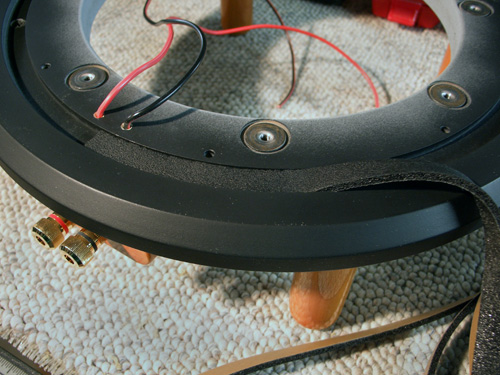
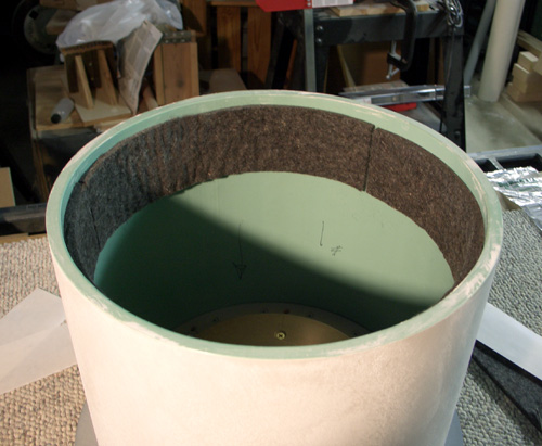
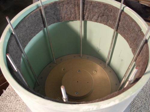
Sun Dec 16, 2007 6:52 pm After the legs had been secured in position with 1-1/4" screws, I placed the Parts Express speaker gasket tape in the groove cut for it in the bottom plate. You can see how the leg screws and legs are directly under the slot for the pipe to maximize load carrying in case someone sits on the sub. Placing the screws inside the assembly also hides them from view. The gasket tape goes over those screws which are countersunk flush in the groove. The next step in assembly was to cut the felt and stick it to the inside bottom of the pipe. I cut in in 2-1/2" strips on a paper cutter, and it took exactly three strips cut from a 12x12" piece to go around. It's purpose is to press against the rods to dampen any sound they may produce in resonance. After attaching the felt, the next step was to take the 12" sections of threaded rod and screw it into the Hurricane nuts encapsulated between the MDF layers of the top assembly. I put a drop of blue Loctite on the end of each one before threading into the Hurricane nut. I had to work quickly here because the Loctite could set up before I tightened everything together. I placed the clear vinyl tubing over each rod, and clipped it to length. Here's a shot of the inside after those steps had been completed awaiting attachment of the bottom plate... |
| Assembly 2 | |
|
Sun Dec 16, 2007 7:00 pm As I mentioned previously, I had to work quickly after the Loctite was applied to the Hurricane nut end of the all-thread rods. I had to get the bottom plate in place, and then tighten the nuts that hold it on. Tightening the nuts also tightens the other end of the all-thread - and the Loctite would secure it there. I used rubber washers, flat washers, and Nylock nuts to clamp everything together. The rubber washers were purchased from the local hardware store and are to provide air-tightness where the rod passes through the bottom plate. (This obviously is the unit where I attached the binding post strip after assembly - not the best. The second unit benefitted from a little hindsight learned from this first one.) Then I attached the driver and did the SL-suggested press-down test for airtightness. It barely budged against the air trapped inside! |
| Finished! | |
|
|
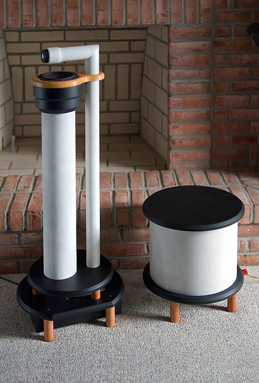
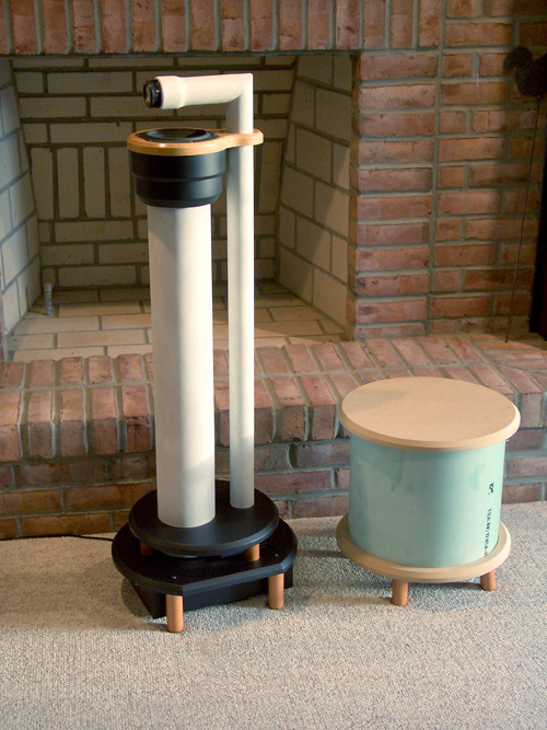
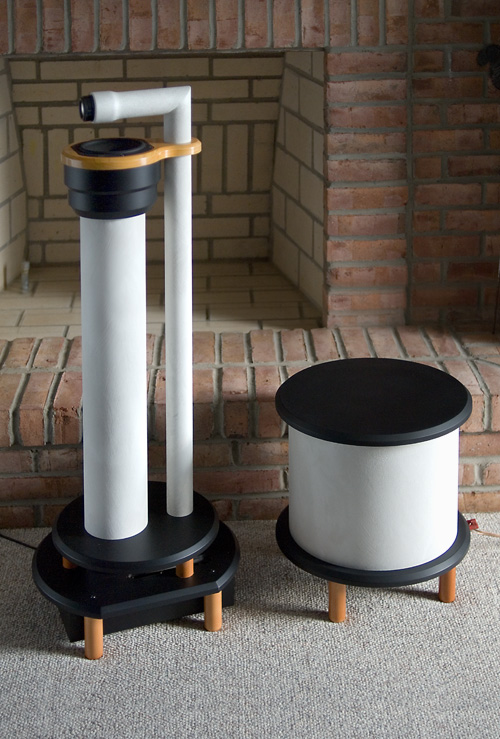
Mon Dec 17, 2007 12:31 pm Time for a couple "beauty" shots of the Pluto+ subs... Here's a sub with its natural companion... They make a fine pair! And a couple detail shots - one that shows the lime wash texture nicely, and the other showcasing the wood accents. BTW, the wood was humble poplar. That's all for now. |
| First Sound | |
|
|
Tue Dec 18, 2007 4:17 pm Got the Brystons hooked up! Instead of buying any additional hardware, I merely soldered RCA plugs on one end of the XLR patch cables according to instructions on this web site: https://www.ranecommercial.com/kb_article.php?article=2107 It works! While the cheap receiver was attached to the subs, I had heard an odd sound from the subs when playing organ music (Reference Recordings 30th Anniversary Sampler, track #11 - Bach: Prelude in D, Virgil Fox on the organ). I suspected clipping because of its low-power rating. The newer Bryston 2B-LP is rated at 60 w/ch unbridged, and 200w when bridged in mono into 8 ohms. I'm using it bridged to power one of the two channels. The older model Bryston 2B (no "-LP") is rated at 50w/channel unbridged (unknown wattage when bridged - I don't have the literature for it) and I'm using that for the other channel. The older Bryston indicated clipping on it's LED indicator during the two loud LF sections of the organ music, and the clip indicators stayed red for a whole second or two. There must be some serious LF in there to suck out that much power! I'll have to be careful when playing organ music. I still need to measure the system now to balance the differences between the two amps. |
| Further Experiments | |
|
|
Wed Dec 19, 2007 2:52 pm I'm still tuning the system, but one probable cause of the clipping yesterday was that the w-asp was set to deliver too much gain. It became apparent on other CDs that bass was excessive. I've now got the pot turned down to the minimum ("7 a.m.") on one channel and slightly above minimum on the other. I suspected that I'd have a little more gain than the recommended ATI with these Brystons running 200w each. If I need to throttle bass back even more, the gain pots on the fronts of the Brystons do that nicely. On another note, wife suggested that I build another set of Plutos for the TV room upstairs. Apparently she's grown fond of them for their funky design. We'll see - I need time for other things right now. |
| Amplifier Gain Experiments | |
|
|
Wed Dec 19, 2007 5:48 pm I've been measuring gain on the Brystons. Generally a 0.5v (60Hz) signal provides a ~26v or ~29v output at full throttle (depending on which amp), but that's with no load on the outputs. The DMM has a high impedance (minimal current draw), so I don't know if setting the gain knob to provide 12.5v (25x) will actually deliver that much gain when connected to a real-world 8 ohm load. |
| More About Gain | |
|
|
Wed Dec 19, 2007 9:19 pm With a 1/2 v input, I measured 29v output on the 2B (bridged). If I calculated correctly, this is a 35dB gain. I did turn down the gain pots on each Bryston to reach Cameron's suggested 25:1 v/v ratio (28dB), then turned the trim pots on the w-asp to their 'noon' position. It sounds very balanced now without excessive bass. It gets better each day. |
| Afterthoughts | |
|
|
Sat Dec 22, 2007 1:39 pm Long-winded wrapup report follows... After every project I like to reflect on things that went well and things that I'd do differently. Undertaking this project is fairly straightforward except for trying to find round PVC pipe material (or concrete form-tube, etc.) to do the job. If you read the earliest posts, you see that I had planned to use Schedule 40 PVC pipe, but alas I wasn't able to find any. A local plumber had 12" low-pressure sewer pipe with about 3/8" wall that I settled for. It works fine, but there's something about a really hefty Schedule 40 wall that satisfies me. Cutting the round plates is easy with a plunge router and a Jasper circle guide (and even easier if you rough cut on a bandsaw first), but not as easy as cutting straight sections on a table saw. You take your pick... Detailed parts drawings on previous pages in this thread have been (mostly) updated. This may help someone who wishes to build Pluto+ subs like these without having to spend so much time measuring and redesigning. However be careful of your pipe diameters if you use different pipe. The finish used for these is different. I believe this unusual finish is appropriate for unusually designed speakers like the Plutos. The lime wash in particular adds texture to the mix of satin paint and glossy finishes on the wooden accents. I like the combination. I do wish the Pluto+ looked a bit more decorative though. If the top had a decorative wooden inlay or a ring of hardwood on outer edges of the top plate, it would improve its appearance. The wooded dress plate on my Plutos that the mid-woofer mounts to is an example of adding a finishing touch to the design. However adding these touches would increase the work and expense. By the way, the Zinsser products used for undercoats (BIN primer for the PVC pipe and Seal Coat for the MDF) make life REALLY easy. The BIN sticks very well to the PVC, and the Seal Coat makes finishing MDF so much easier. I had used the Plutos without Pluto+ subs for several months, and grew to like the very Spartan system of only the Plutos and an Oppo CD deck. There was something very appealing about an excellent sounding system with so few components - not even a pre-amp. Small footprint, minimal external electronics, and huge sound. The little sound system that could... Adding the Pluto+ complicates things with external crossover/eq plus the separate amp(s), and more wires strewn across the floor. It also occupies additional footprint. There's no doubt that it fleshes out the Pluto sound, but in a strange way, it feels like an innocence is lost too. (Good gosh - that sounds mushy!) Be careful to employ an amplifier that has the proper amount of gain to match the design targets of the w-asp electronics. It looks like 26-28dB is about right (around a 25:1 voltage gain), although I couldn't find specifications for it in the Pluto+ documentation. I'm grateful that my second-hand Brystons had gain control knobs on the front to take gain back down to a the needed level after they were bridged. New Pluto builders have the new Seas driver available that adds a bit to the lower frequencies, and they may be perfectly happy with a minimal system. If I were building a new system with the Seas drivers, I might just stop there. (Yeah, right...I know how guys like me are - never completely satisfied) Regardless, Pluto+ considerably improves the sound of the original Plutos with Peerless drivers. Nothing good comes without cost though. I'll put up with more wires, less space, and additional glowing bezels for this sound. It's been a fun project - actually easier than I expected. Thanks to everyone who contributed ideas and comments along the way. Time for me to go listen to music... :D |
| Footnote and Some Measurements | |
|
|
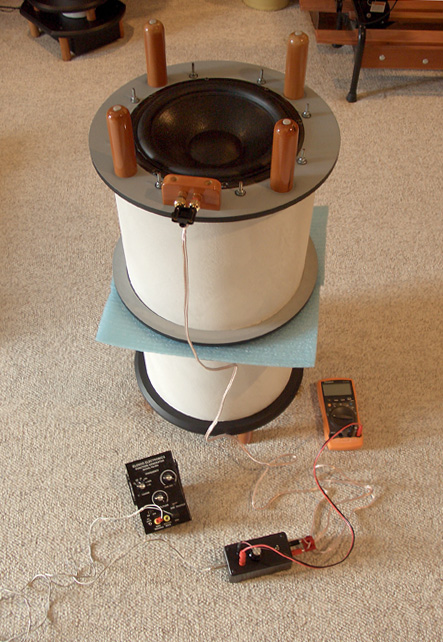
Sun Dec 30, 2007 8:27 pm And now... Here's a little footnote in the evaluation of the Pluto+ subs... Today I measured the woofer's impedance at various frequencies to calculate f0 and Q0 according to information given on the Linkwitz site at... http://www.linkwitzlab.com/images/graphics/f0Q0.gif I went to Radio Shack and bought a bunch of banana connectors, a pot, a switch, some resistors, and a project box to house the circuit. Astonishingly, it came to about $50 for everything. I should have spent a little more and purchased the Parts Express WT3 woofer tester now on sale for less than $100. It appears to automate this info collection, and probably has higher accuracy than my hodge-podge of parts. At any rate, here are the numbers for my Pluto+ in enclosures .. The targets given on the Linkwitz site are f0 = 74.3 Hz and Q0 = 1.57. The f0 is fairly close, but my Q seems a little lower than the target. The subs sound very good, so I'm more curious than concerned. |
| More F0 Q0 Experiments | |
|
Mon Dec 31, 2007 12:33 pm I have listened to them for a couple weeks now I ran another round of tests with one of the speakers inverted, and on an elevated surface (I used the other Pluto+ as the 'stool'). It didn't change much from the first measurement. The numbers are below: F0 -------- normal orientation - 72Hz inverted orientation - 71.7 Hz Q0 ----- normal orientation - 1.14 inverted orientation - 1.12 It's curious that my Rdc (voice coil resistance to DC) is so much lower than SL's for this driver. That shouldn't be affected by the enclosure design - it's just dc through the voice coil. Perhaps a driver modification has occurred? I checked the Rdc of both woofers with two different meters and they agree. If I take out the interconnect cable and test dc resistance at the binding post, Rdc drops to 5.7 ohms. I also find the impedance to various frequencies significantly higher than SL's. This could possibly be explained by my flea-powered frequency generator becoming current starved at the lower impedances, and benefitting from the higher impedances to deliver more voltage. I'm putting two volts into the test jig, and I've had to lower the 600 ohm current-limiting resistor in the jig to 350 ohms to get the suggested 0.01v just past the current limiting resistor. The two volt input drops significantly under test load. There are a lot of variables at work here. The good news is that it sounds good, but all this makes me very curious about the difference in measured parameters. I'm almost ready to pony-up for the WT3 woofer tester from Parts Express just to learn a little more about this.. |
| Measuring Wrap-up | |
|
Sat Jan 05, 2008 2:57 pm I used a very inexpensive frequency generator kit (~$50) from Parts Express - one that I built as a "warm-up" before tackling the Pluto circuit boards, and afterward used to check the Pluto boards once they were assembled. It's a budget item, and it has a non-calibrated frequency pot that is non-linear in its operation. At the upper end of the 10-100Hz frequency range, each frequency jump is around 2 or 3 Hz with the smallest tweak of the pot. I use my DMM to read frequency, then switch to voltage mode for a measurement. In an attempt to get my f0 and Q0 closer, I removed the 10" driver to insert more MDF into the enclosure to reach the specified f0 target of 74.7 Hz. I first just inserted loose pieces of MDF, had the unit upside down, and reached f0 of 74.9Hz and a Q0 of 1.23 - an improvement. F0 was actually slightly beyond the target. However when I screwed the additional MDF disks into place, I measured them in-place in their normal position (right-side up) and found f0 dropped to 73.4 Hz and Q dropped to 1.16. Both these numbers are slightly better than where I started a couple days ago, but don't match SL's specs. I'm satisfied that f0 is about as close as I can get, but in my opinion Rdc of the driver would have to increase to achieve the target Q0. SL shows an Rdc of 6.53 on the graph given in the first page of the Pluto+ information. While my DMM begins to object to low-frequency measurements (dithering voltage numbers on the display at my lowest frequency of 9 Hz), I could also achieve an Rdc in the mid-sixes if I merely used the projected asymptote of the curve shown below, and be in very close agreement. There appears to be a measurement discontinuity between an ohm-meter Rdc point and that of the projected 0Hz limit of the impedance curve. This makes me curious. Is my problem one of measurement? |
| Comment from Davey on the OPLUG Forum | |
| Mon Dec 31, 2007 12:53 pm Bill, Try your test again but include your power amp in the mix vice driving the speaker directly with the signal generator. Set the level so there's at least 5 volts output from the power amp. You should be able to switch back to the 600 ohm resistor and get a pretty good constant-current measurement. |
|
| Comment from Seigfred Linkwitz about Measurements | |
|
|
Sat Jan 05, 2008 4:36 pm Bill, Before analyzing your f0, Q0 measurement procedure and possible differences in drivers and enclosures from what I had at the time, I would simply make an acoustic measurement to see what you have got. Set up your sub normally and place a microphone about 1 inch in front of the dust cap. Measure the equalized frequency response. If it is close to what was expected, then you are done. As you have noticed the measurement and calculation of f0, Q0 depends on several physical quantities that can vary. They also are small signal parameters while the driver is certainly not operated at small signal levels. So the whole thing is just an approximation. The measurement will tell you what you really have operationally. SL |
| Conclusions | |
| I spent a lot of time measuring when I could have trusted my ears. These subs are an exceptional addition to the original Pluto loudspeakers. They take them into a new realm, and the combination can reproduce with both quality and volume. Superb! | |


